Hello ,
Waiting for my driver to arrive so i have some time to write down some information on lundahl chokes. For the dddac there are 3 that can be used.
LL2771 The BIG one 3H 1A or 6H 0,5A 2 times 5,6 ohm dcr 131,99 euro
LL2733 The not so big one 0,4H 1,7A 2 times 1,7 ohm dcr 96,53 euro
LL1694 The little one ( the one most people use for the dddac) 0,16 H 2 times 0,9 ohm 75,31 euro
My honest opinion is that you should use the BIG one as the first choke. The higher the number of Henry the less current it needs to work perfectly. Some people say the Tentlabs shunts will start using current right after switching on. I want to have some extra safety so that is why i use a resistor across the first capacitor to make sure there is ALWAYS a minimum current taken from the power supply .
Some people will worry about the dcr of 5,6 ohm of the big choke but because the Tentlabs shunt will give the power supply a constant load i dont think this a big problem.
If you have doubts about that you could use a choke with lower dcr as the input choke but the you will have to use another transformer as well because the ll2771 will give much higher voltage drop than tne two other lundahl chokes.
By the way i have a vietnamese friend who use the ll2733 for a choke input power supply for a Nelson Pass class A power amp. One might think that there there the two times 1,7 ohm would be a problem but probably because it is a single ended class A amp with an output transformer there is no problem at all.
Greetings, Eduard
This is great data! My new dac will be 8 or more boards so I will need to have a play
Hello Simon,
If you use 8 boards dddac you will need a choke with a higher current rating.
Lundahl offers the possibility of order the same choke with a different airgap. So for my tube power amp i got the ll2771 with a 0,1 A current rating so a much higher number of Henry.
But with two A current rating needed for 8 boards with shunts you will end up with an ll2771 with 1500mH which is still impressive. But you will have some difficulties finding the right transformer in the Triad transformer i mentioned because of the 2A and you will need a much higher ac voltage on the secundairy side because a 2A load will give a big voltage drop across the input choke. You might even end up using two to compose the right current rating. If the combination can supply 3A or more it will be ok because the transformer will have a much easier task with a choke input filier
Lundahl tells in their transformer datasheets that current rating is 63% with capacitor input and 95 % with choke input using the same transformer because with choke input there is a constant current and with capacitor input the charging of the power supply will be done with pulses generating much more heath and other side effects as well!!
Greetings, Eduard
Yes I know more I needed
I will sit and wait as I might go as higher on the boards. My main DAC has choke PSU with 4 old boards and 4 tent boards and all is well with 2 x 2733 chokes
I will sit and wait as I might go as higher on the boards. My main DAC has choke PSU with 4 old boards and 4 tent boards and all is well with 2 x 2733 chokes
Yes I know more I needed
I will sit and wait as I might go as higher on the boards. My main DAC has choke PSU with 4 old boards and 4 tent boards and all is well with 2 x 2733 chokes
Hello ,
Maybe it is a good idea to try a made to measure ll2771 that can as much current as you need for the present 8 boards!! I am sure there are enough people willing to buy one of your ll2733. Then you have to look if there is a Triad split bobbin with the right voltage and current rating. Just in case you could use two transformers because they are not expensive at all.
As far as i know nobody using the ll2771 for the dddac. Only have a friend using it in the Hiraga class A power amp for a CLC supply. Was build by me 30 years ago with 200mH chokes now it has bigger ones.
Greetings, Eduard
Current is fine for the current 8 boards and all working well Edward. I wil lpause on this second PSU now I have the facts and data I need. I need to finalise how many DAC boards I will end up at so for now i will use the DDDAC PSUs and mod to ensure the 12v one can deliver the extra current needed - simples
Hello,
It seems there are only very few people using eight boards or more. Especially if all of them have shunts one usually also needs to make a bigger step with the power supply too.
I made the new supply some months ago and i think the biggest improvement next to be made is using fifopi and some 3,3 volts power supply i improvements.
Greetings, Eduard
P.s already found the 3,3 volts lifepo4 much cheaper in my country
Yes I agree
I have the fifo and best clocks already and will purchase the battery supply and super caps
Increasing the 12v PSU is easy and done this already
Can you share the link to the cheaper place?
I have the fifo and best clocks already and will purchase the battery supply and super caps
Increasing the 12v PSU is easy and done this already
Can you share the link to the cheaper place?
Hello,
I read somewhere that the power supply of the clock is a very critical one. And it seems that 3,3 volt from Ian is the best available. Of course we dont know if this is true. If people who say this are not making money when they say this it could be true.
The batteries can be found at nkon.nl website.
Greetings, Eduard
SURE, at first one could think that it is a hobby. It is but the commercial boys know exactly how to trigger the people to keep spending their money.Hi - this is business and the hifi industry is full of snake oil 😉
Of course all of us think we will not take their funny stories but in fact most of us do.
As long as we dont end up bankrupt. Just dont spend money you cannot miss or have not in your wallet yet.
Dont raise your mortgage for new cables!!
Greetings, Eduard
...the next step is to build (parts are ordered) a PI3 B streamer with RoPIeee software running under ROON of course with the FiFoPI as described above. Than we will compare Aurender-USB-WaveIO with the PI setup…
To be cont’d
Any updates on this already? I am in the RPi camp, so...
Any updates on this already? I am in the RPi camp, so...
haha patience please. I had to rewrite the arduino code for the DDDAC Control - I am about to upload and test it, then there is an option to select from two I2S sources with the IR remote controll and I have the Aurender/Wave and PI/Ian running at the same time with the same track and I can do real A-B comparing - but, I have to do some soldering as well to get the boards in - I do have the boards here already 😛 stay tuned !!!
haha patience please. I had to rewrite the arduino code for the DDDAC Control - I am about to upload and test it, then there is an option to select from two I2S sources with the IR remote controll and I have the Aurender/Wave and PI/Ian running at the same time with the same track and I can do real A-B comparing - but, I have to do some soldering as well to get the boards in - I do have the boards here already 😛 stay tuned !!!
Exciting!

Hello,
Yes, we should be patient so it will be comparison between two things that both have been set up in the right way. AND it also should be two solutions that can be rebuild by dddac users and work in a consistent way with every user. It seems that are quite a bit of circuits that can be added to the dddac but not everyone gets them to work the right way. Sometimes it is just a very small thing that is neglected but will stop the whole combination from working perfectly.
The permanent introduction of the Tentlabs shunts and the famous other mod took some time too but everyone agrees it works.
So we will give Doede a few weeks/months so we can all make our personal opinion on how much money and time we are willing to spend on the next upgrade.
It will probably be a lot cheaper than the Aurender that will end up in the attic?
Greetings, Eduard
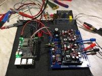
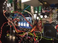
Well said Eduard ! Sure it will not take months I hope. At least a good start. On the picture you see the test setup. Everything worked fine from the start... Next step, build it in my music room DAC 😎 ps This works over WiFi .. I will also listen to wired and WiFi
Attachments
Hello,
Just looking at the quality of the probes is one more reason for me to let Doede do some testing.
He is using the same Aurender connected with the wave io to the dddac. Improving this with a few simple and not to expensive mods would be nice. BUT audio creative did some test with replacing the wave io with a non usb connection but that would also mean exit for the Aurender.
Doede will also try this so that could be a second step.
If there are some things that can be used to upgrade the present wave io/ Aurender combo and that could later be used to make a more drastic change that will be ok.
Fifopi and the lifepo4 board from Ian, some ultracaps and some clocks will be on the orderlist for sure.
Greetings, Eduard
Well said Eduard ! Sure it will not take months I hope. At least a good start. On the picture you see the test setup. Everything worked fine from the start... Next step, build it in my music room DAC 😎 ps This works over WiFi .. I will also listen to wired and WiFi
Looking at the photo it seems you are feeding the FiFoPi like this:
- add-on SMPS for the RPi power
- DDDAC board for the "clean" power
- Everything at 5 V
Looking at the photo it seems you are feeding the FiFoPi like this:
Correct?
- add-on SMPS for the RPi power
- DDDAC board for the "clean" power
- Everything at 5 V
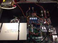
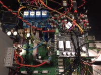
Correct, BUT ONLY for the first functional test. I built everything in my DAC yesterday evening (for testing again, not final assembly 😀 )
I power as follows (this will be final for now)
*DDDAC Board - Magic Power Supply (Audio Creative) 12V
*Wave IO - DDDAC 5V
*PI3 + FiFo (the stacked / non-isolated part) and the Relais Board - 5V SMPS
*FiFo - Isolated Clock Part - LDOVR 3,3 Volt through RC coming from Magic 12V
*Arduino Control Board - Small LM317 PS 12V
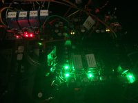
see the pics (Christmas is over, but it lightens up as a Christmastree 😛 )
Will do real listening tests later this week
Attachments
*FiFo - Isolated Clock Part - LDOVR 3,3 Volt through RC coming from Magic 12V
Just to be sure I get this right:
Magic 12 V PSU --> DDDAC board --> LDOVR on DDDAC board 5V* --> RC filter (drops to 3.3V output) --> FiFo
(*) this is where normally the WaveIO isolated I2S part is connected
The RC filter between the DDDAC board and the FiFo might be nice because it decouples the regulator from the FiFo, so the "imperfect" load response of the regulator is "hidden" behind the RC filter, and the load response is controlled to a large extent by the C of the RC filter.
next level clocks....
Was refered to this by someone how knows his stuff.
Because everybody talks about the Accusilicon clocks as reference, this should be the creme the la creme.....it'll cost you though.....
NewClassD NeutronStar2 25.000
😉 Paulus
Was refered to this by someone how knows his stuff.
Because everybody talks about the Accusilicon clocks as reference, this should be the creme the la creme.....it'll cost you though.....
NewClassD NeutronStar2 25.000
😉 Paulus
- Home
- Source & Line
- Digital Line Level
- A NOS 192/24 DAC with the PCM1794 (and WaveIO USB input)