@Doede
I see on your pictures that you have 6 wires on J7. Do you have one gnd wire for each i2s signal wire ? I’m asking because I only use one gnd wire for the i2s signal wires (it work’s fine with one gnd wire). But I don’t see a gnd wire for i2s on J1, only wires from dddac mainboard for i2s signals, + 5v and gnd.
I’m asking because I’m still learning. 🙂
Well spotted Tommy! As I have the flatcable, it is by (waveio and mainboard) Design that every second wire is GND. I just thought it would be a good idea to connect all 3 GND wires which are between the I2S signals to the FiFo GND (pin 6 ) but it also works with one ground wire of course.
REALLY!? Wow, what a conicidence! Exactly 15 years... 😉
Noooo, don’t tell me you are feb 5 too ?
Thanks Edward
I did build a choke PSU for my main DAC now playing with another DAC build.
I remember my first choke PSU was very difficult to get the transformer voltage and bleed resistors correct to get the 12v needed to fed the DAC
Hello,
It is not to difficult but the voltage also depends if you use low or normal voltage drop diodes.
The value of the resistor can be calculated and you need to use a decent safety margin.
The capacitors can be protected with a big wattage zenerdiode so the voltage will not rise above the maximum admissible voltage for the capacitor and the 7810 regulators ( idea given to me by Guido Tent) . If you need the right value bleeder in combination with the LL2771 the voltage will already rise very gradually at switch on.
But better be safe than sorry.
Greetings, Eduard
Hello,
I know it will feel like a birthday after i connected the dddac with its new power supply to my yet to finish tube line amp.
The line amp will be the same like the one before only difference will be a new chassis and replacement of the Allen Wright solid state shunt supply with a tube shunt supply. Both high voltage supplies have choke input but i expect the tube supply giving me something extra.
The effect of a bigger choke in a power supply ( and i have made several upgrades in the 30 years i have been using choke inputs!!!!l) soundwise will be several. It doesnt differ that much if the change is made in dac, pre amp or power amp.
One of the things that happens is that the device sounds as if it has an easy task to be done. It can be compared to reading a paper book on a well lit terrace in a comfortable chair to looking on a paper map on the back of a small motorbike in the highlands of Vietnam. Yes the view is nice but you have to focus on the map.
Much more information is taken from the source and presented to you in a musical way. There is detail but it is the music that should be presented to the listener.
Here in Vietnam, you can get a coffee for less than half a $ , made from freshly grinded beans, with the help of a simple water cooker and a filter composed of some metal parts that make it drip into your cup with the speed of one drop a second OR you can get your coffee made with the latest state of the art Western coffee machine. A choke input is a simple but effective device like the metal coffee filter as long as you use the right beans and grind them just before making coffee it will work for decades to come. The 4000 $ coffee machine will probably last a few years and when maintenance is needed parts are out of stock.
So with choke input it is much easier focussing on the music than on things you did not hear before. When the music start you should be drawn by the music not by the technique.
There are photos made with very simple cameras 70 years ago compared to cameras everyone is using now and still 99,9999% of todays photos are crap. A well designed choke input ( not to much can go wrong if you focus on a few things) offers a good start for most power supplies.
greetings, Eduard
hello DD
was curious about how you ended up with KALI and then now this Fifopi
I´m up&running with my Fifopi too
maybe my first works too? this new one works fine with 5v but it flashes from empty to I2S in only when I start playing...
anyway most important...how do you like the sound?
best
Leif
was curious about how you ended up with KALI and then now this Fifopi
I´m up&running with my Fifopi too
maybe my first works too? this new one works fine with 5v but it flashes from empty to I2S in only when I start playing...
anyway most important...how do you like the sound?
best
Leif
Hi guys, most of my PSU parts arrived (still waiting on the choke and the rectifier board so I'll have to wait until i can play around with the resistors (bleeder and filter) to see what voltages I'll actually end up with the 2x30v toroidal and sven sjorstroms rectifier bridge combo and the LCRC filter i designed with PSUD (thanks again for the tip smooth dancer). I guess it won't be the most efficient PSU but at least i have room to play around with the resistors 😀
Before i blow something up i'd appreciate a little confirmation that this is ok in terms of modding Doedes PSU (see picture), and what DC input voltages i should best aim at (4 board dac)?
Thanks in advance and happy new year everbody 😉
Before i blow something up i'd appreciate a little confirmation that this is ok in terms of modding Doedes PSU (see picture), and what DC input voltages i should best aim at (4 board dac)?
Thanks in advance and happy new year everbody 😉
Attachments
Looking fine Hifoli. I have 21vdc in on dddac 12v psu. I measure 60˚ on the reg, and this is ok according the specs for this reg. As long as you give the regulator around 10v (+-2-3v)to work with, you will have no problem with over heating the reg.
I ended up ordering wirewound resistors in different values to have the possibility to fine tune the voltage.
I ended up ordering wirewound resistors in different values to have the possibility to fine tune the voltage.
Last edited:
Hello,
In post number 7159 i wrote down some data i got when i am using the big ll2771.
To me it would not make much to much sense to combine the original 12 volt supply with a choke input and use that combination to supply 12 volt to the 7810 regulator which then will be used to make the 10 volt input for the Tentlabs shunts..
With a 30 volt transformer, the right diodes, ll2771 as input choke after that lc or rc network you get the right output you need to supply the mainboard.
Greetings, Eduard
I’m not going for a choke loaded supply this time. Perhaps my last post was misleading I’ll go for a CLCRC (not LCRC as postedbefore) like smooth dancer, with a big toroidal and a ll1694 choke instead of choke loaded and small transformer like I did on your info for my 5V psu.
Greetings
PS: i know your a big choke fan but this time I’ll take the other approach with the big toroidal😉
To use doedes supply seems good in anyway to me, as it’s practically a RC filter design which doesn’t need big caps (I think it’s called capacitance multiplier, so just more filtering and a trim to regulate and that’s always good to use i guess 😀
Last edited:
I’m not going for a choke loaded supply this time. Perhaps my last post was misleading I’ll go for a CLCRC (not LCRC as postedbefore) like smooth dancer, with a big toroidal and a ll1694 choke instead of choke loaded and small transformer like I did on your info for my 5V psu.
Greetings
PS: i know your a big choke fan but this time I’ll take the other approach with the big toroidal😉
To use doedes supply seems good in anyway to me, as it’s practically a RC filter design which doesn’t need big caps (I think it’s called capacitance multiplier, so just more filtering and a trim to regulate and that’s always good to use i guess 😀
Would you mind posting a drawing of the circiut so its clear the changes to be made to Doede standard PSU please?
Would you mind posting a drawing of the circiut so its clear the changes to be made to Doede standard PSU please?
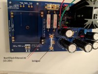
Doedes psu stays pretty much the same, I just don’t put the transformer and rectifier diode on and instead connect like in the picture I posted before.
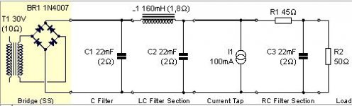
So I’ll feed the psu with already pretty clean dc from a 300VA 30V toroidal and a CLCRC Filter like in the picture below (be careful the values in the diagram are quick estimates, I’ll need to get those straight once I have everything set up and can measure)
For rectification i ordered a board for a full wave rectifier from Sven sjorstom, not sure if there is an advantage over my self made full wave rectifier bridge I used on my 5v but it certainly looks nice and the board is not expensive. So pretty much a clone of smooth dancers design 😉
(I will post a round up review once everything is complete, i can give you the exact values I used then...)
Attachments
Last edited:
Doedes psu stays pretty much the same, I just don’t put the transformer and rectifier diode on and instead connect like in the picture I posted before.
So I’ll feed the psu with already pretty clean dc from a 300VA 30V toroidal and a CLCRC Filter like in the picture below (be careful the values in the diagram are quick estimates, I’ll need to get those straight once I have everything set up and can measure)
For rectification i ordered a board for a full wave rectifier from Sven sjorstom, not sure if there is an advantage over my self made full wave rectifier bridge I used on my 5v but it certainly looks nice and the board is not expensive. So pretty much a clone of smooth dancers design 😉
(I will post a round up review once everything is complete, i can give you the exact values I used then...)
Thanks! Be interesting to understand where the choke is in the Doede PSU
The choke is BEFORE Doedes psu, (nr two after the trafo 160 mH,1,8ohm).
After the psu shown on the pic follows Doede psu.
Maybe eduard is right, but it sounds damn good in my setup as it is now, and easy to regulate voltage if needed.
After the psu shown on the pic follows Doede psu.
Maybe eduard is right, but it sounds damn good in my setup as it is now, and easy to regulate voltage if needed.
Last edited:
Diy is fun, but for me is diy also a way to be able to get a sound at least as good as the commercial stuff out there, at a much lower price.
Look closely on this dac on the picture here. It’s a Berkeley Reference, and the price is very high. When it came out on the market I think it cost between 15-20000 usd.
A was so lucky to have it for a week in my setup for a shootout against my dddac. Berkeley came from a dealer and have been used for demo’s, so it was fully burnt in.
Berkeley and my dddac was quite even in sound quality, but when it comes down to the lower frequencies, Berkeley had no chance . Dddac with big psu have more autority and slam when turning up the volume. An example is Nick Cave’s «red right hand», the big drums in the background had more slam and better decay. This tells me that a beefy and well filtered psu is the key, and this is easy to hear here with me on JBL-4365, powered by McIntosh 1.2kw.
After Ian’s fifopi, it’s another step forward.
Attachments

I agree good fun and cheaper
This is the psu design where the choke replaced the 0.1
High power DDDAC power supply
This is the psu design where the choke replaced the 0.1
High power DDDAC power supply
My Review of the Ian Reclocker FiFoPi
My Review of the Ian Reclocker FiFoPI 2020-01-02
I had the Ian on power for two days now and did several listening sessions. As word goes around it would take a few weeks for burn in, fine I couldn’t wait, so it only can get better? But for now it was clear what happened. So here is my review:
I was playing:
Aurender N100 – USB – WaveIO on 5V standard DDDAC power supply – “Blue” mainboard on 12 Volt standard DDDAC Power supply – 8 decks of “old” DAC module (no shunts no pin 20) – Sowter TVC output
I use this rig for tests as it is built on an open chassis, making things easy. The TENT versions are clearly better, but I thought, if the reclocking is audible and noticeable on this one it for sue will deliver similar results on the new DAC…
I have been listening to a couple of studio- and live -tracks with pop, jazz, blues and classic – mix of CD and 192kHz formats
The set up was made so, that I could easily switch (literally a switch) between situations back and forward with max 10 seconds delay – so almost a true A-B comparison
The observations below are all in relation (relative!!) to the standard WaveIO connection without Ian FiFoPI. The differences are small (as always in high end?) but clearly audible on most of the tracks…
For Nr2 and Nr3 the FiFoPI is powered by the Mainboard 5 Volt LF50 and the WaveIO 5 Volt reduced to 3.3 Volt (see my other posts on this…)
For Nr4 and Nr5, I used a LT3045 LDOVR 78xx regulator I had lying around. They can be very easily (re-)programmed with a single resistor (every 10k = 1 Volt) The regulator was fed by the 12 Volt power supply through a RC (165 Ohm – 47uF) for extra filtering / decoupling and pre drop to 7Volt to limit dissipation of the LDOVR 78xx
1. Standard situation
Of course this is kind of a base line, knowing already how the reclocked sound is perceived… Nice analog spatial sound – sometimes laid back – clear texture but when things get complex, it might get a bit less clear and contoured
2. FiFoPI with standard clocks:
Same as 1, but a slightly more direct sound, sharper contours, but somehow it does not sound well at all tracks – I could imagine getting listening fatigue here. It reminds me strongly on the Kali I tried earlier (I was not impressed by the Kali)
3. FiFoPI with Accusilicon clocks:
More analog sound – you hear it immediately – you automatically lean back in your chair and have a grin on your face – this is what we were looking for. Music is more sparkling, very clear contours and improved texture of voices and instruments. Space is better defined.
4. FiFoPI with Accusilicon clocks and 5 Volt LDOVX 78xx Regulator:
As Nr 3 – but everything described improves again a little bit
5. FiFoPI with Accusilicon clocks and 3,3 Volt LDOVX 78xx Regulator:
As Nr4, and again slight improvement, but now mostly audible on texture of voices
If you go back and forward between Nr 1 and Nr 5 – you know immediately what is going on and the decision to keep the Ian FiFoPI with the LT3045 3.3V regulator is a done deal
In the FiFoPI manual, Ian also describes he prefers batteries of 3.3 Volt, as this is bypassing the on board regulator. Well, it seems, that actually bypassing the on board regulator is delivering the best results when the power supplied is as noise free as it can be – which makes sense of the commonly accepted fact, that good clocks need to be fed with as low as possible noise power supply…
This was really worth it and the next step is to build (parts are ordered) a PI3 B streamer with RoPIeee software running under ROON of course with the FiFoPI as described above. Than we will compare Aurender-USB-WaveIO with the PI setup…
To be cont’d
Attachments

- Home
- Source & Line
- Digital Line Level
- A NOS 192/24 DAC with the PCM1794 (and WaveIO USB input)