X,
You don't need the 4.7V zener; 2.7V is fine, so two series silicon diodes and a green led would do it. And if you don't want the clip, you can delete it.
Hugh
You don't need the 4.7V zener; 2.7V is fine, so two series silicon diodes and a green led would do it. And if you don't want the clip, you can delete it.
Hugh
Hi Hugh,
The clip indicator, will it work with 1N4148, red LED, plus 2.7v Zener? I like red for clip rather than green. Maybe will work on adding the capacitors and transistors tonight.
The clip indicator, will it work with 1N4148, red LED, plus 2.7v Zener? I like red for clip rather than green. Maybe will work on adding the capacitors and transistors tonight.
Yes, X, no issue at all. This gives you 2.7+0.7= 3.4V padding for a 1.6V led. More than enough. As you reduce this 3.4V, the red led lights up at lower peak output and I judged it to give clear clip, not before, at high output.
HD
HD
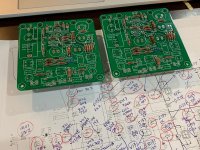
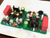
The Alpha Nirvana main board assembly is now complete. I have the snubber boards with their MOSFETs that still need to be assembled, then install in heatsink. I also have to connect my new 600VA AN-6222 trafo to the SLB to get the power out. Connectors for the MOSFETs and speaker outputs also need to be made. These are quite colorful amps!

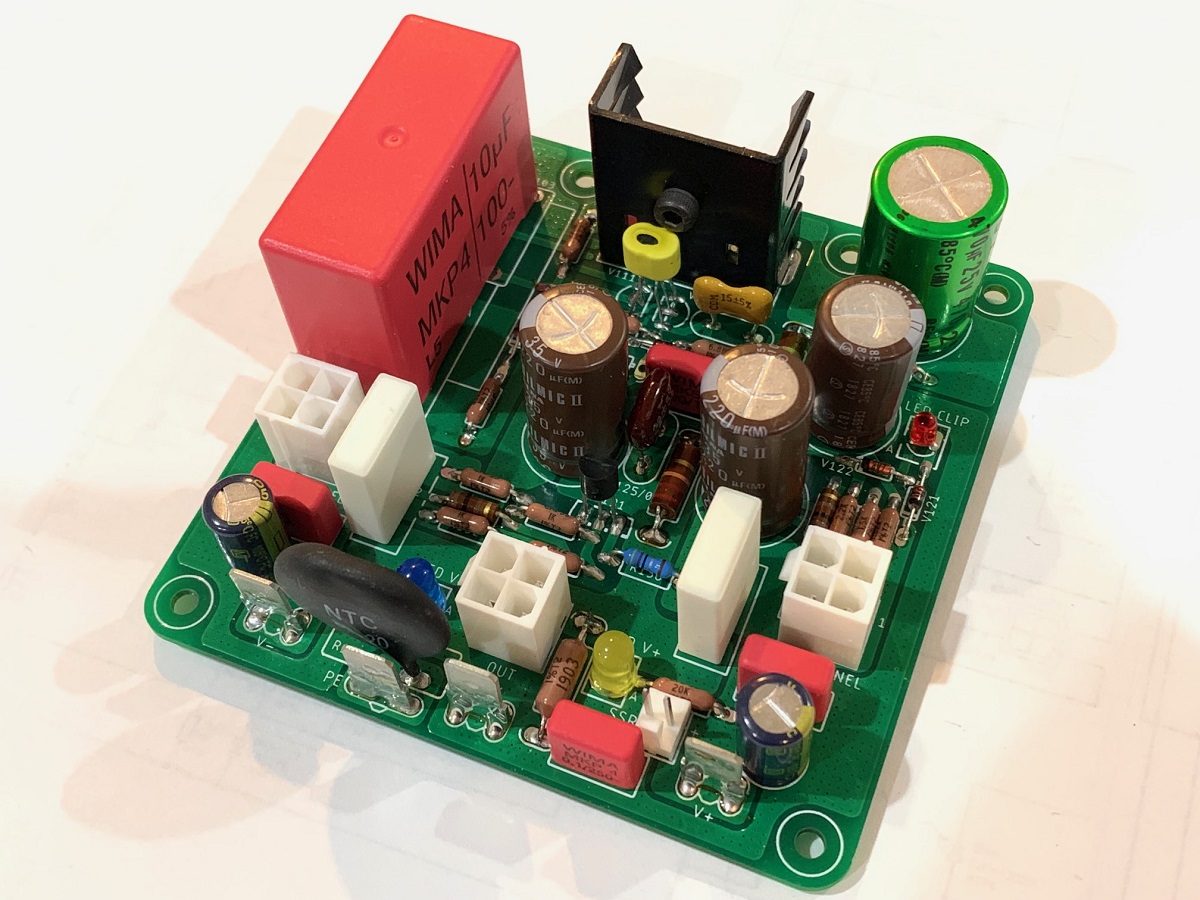
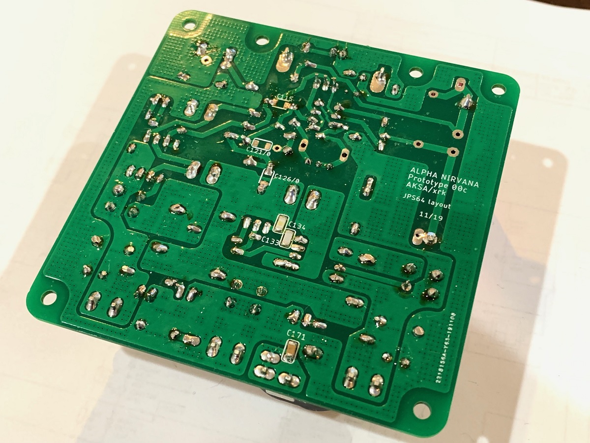
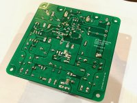
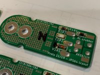
Backside requires installation of 3 SMT caps. There are open spots for more in case one does not want to use silver mica through hole ones on the other side:
Stopping here for the night...
Backside requires installation of 3 SMT caps. There are open spots for more in case one does not want to use silver mica through hole ones on the other side:
Stopping here for the night...
Attachments
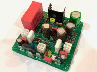
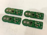
Indeed , they are colourful pcb's X, for once the green solder mask highlights the component colours well, three different coloured LED's, and again no adjustment trimmer pots - even better.
Let's hope the sound quality will match🙂
Let's hope the sound quality will match🙂
Last edited:
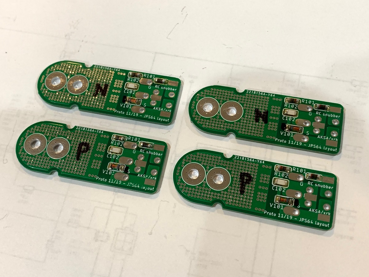
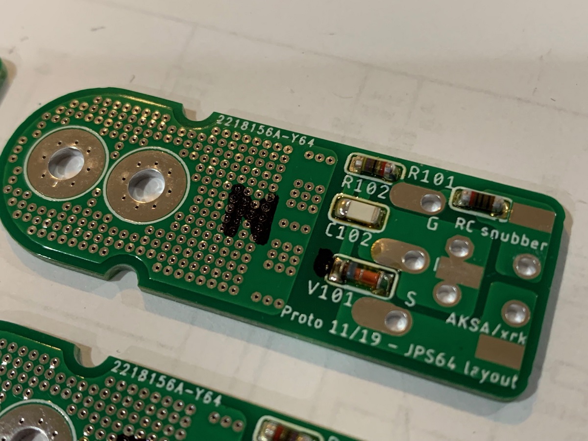
I was going to call it a night but decided to populate the snubber boards with MELF carbon resistors, a zener diode, and a 220pF NP0 cap. These were done with solder paste and a hot air pencil. Note the orientation of the diode for N channel (point to the bolt holes) vs P channel (point to the pins).
Attachments
X, it must be a very late Sat night there for you as I am about to hit the sack here for our Sunday night.
Thanks for the Hi res photos - will be handy for reference.
Thanks for the Hi res photos - will be handy for reference.
Nice X! Can't wait for you to fire up the PS, and get some initial measurements. Was your main board done with hand soldering or was it solder paste + oven?
Get some sleep!
Best,
Anand.
Get some sleep!
Best,
Anand.
Fantastic X!
With Christmas around the corner, the colorful Alpha Nirvana boards would be perfect accents hanging on the tree 🙂
Looking forward to first sound!
With Christmas around the corner, the colorful Alpha Nirvana boards would be perfect accents hanging on the tree 🙂
Looking forward to first sound!
Nice X! Can't wait for you to fire up the PS, and get some initial measurements. Was your main board done with hand soldering or was it solder paste + oven?
Get some sleep!
Best,
Anand.
Thanks, guys. Feeling much better now with some sleep under my belt.
Main board SMT was soldering iron on one (brown X7R). But paste and hot air pencil on the two NP0 caps. It’s much easier.
Alpha Nirvana First Sound
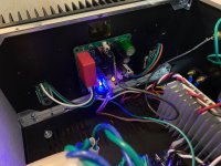
Great news to report is that the Alpha Nirvana fired right up with no issues and not a single adjustment! I have a 22R resistor placed in the PCB header socket (per the simulation) and DC offsets are 5mV on left channel and 3mV on right channel. Quiescent bias current is 1.65A with +28.3v and -28.6v rails under load provided via an Antek AN-6224. PSU is a single SLB. It is playing music now and with nothing connected, I was getting 0.2mV rms noise at the speakers. Connecting my iPhone with 3.5mm to RCA cable is generating a small amount of hum - ground loop I think. I am running the speaker negative from the amp PCB. I think moving the speaker return to the SLB might help.
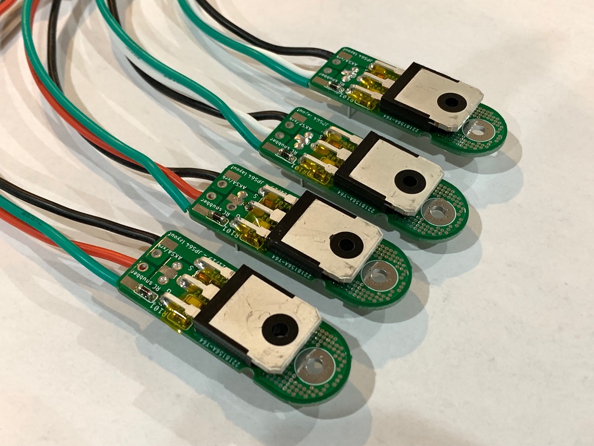
Here are the snubber board with the Fairchild MOSFETs mounted:
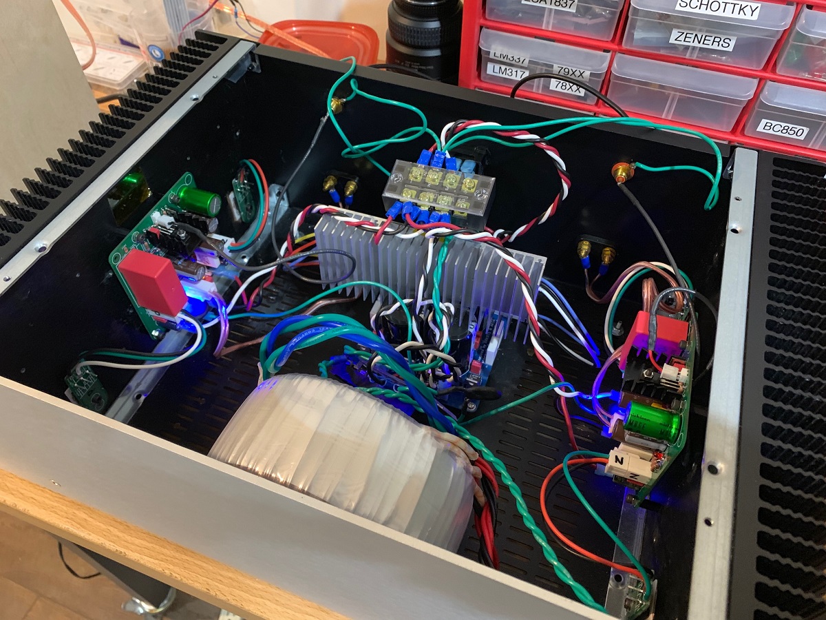
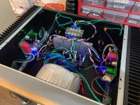
Here is the amp board mounted in a DIYA Store/Modushop 4Ux300mm Dissipante case with UMS heatsinks. The PCB mounts perfectly to the 4 standoffs. I mounted the MOSFETs pretty far away near the edges.

Another view showing the SLB and SLB heatsink. The trafo is mounted towards the front and standing on edge to have enough room.
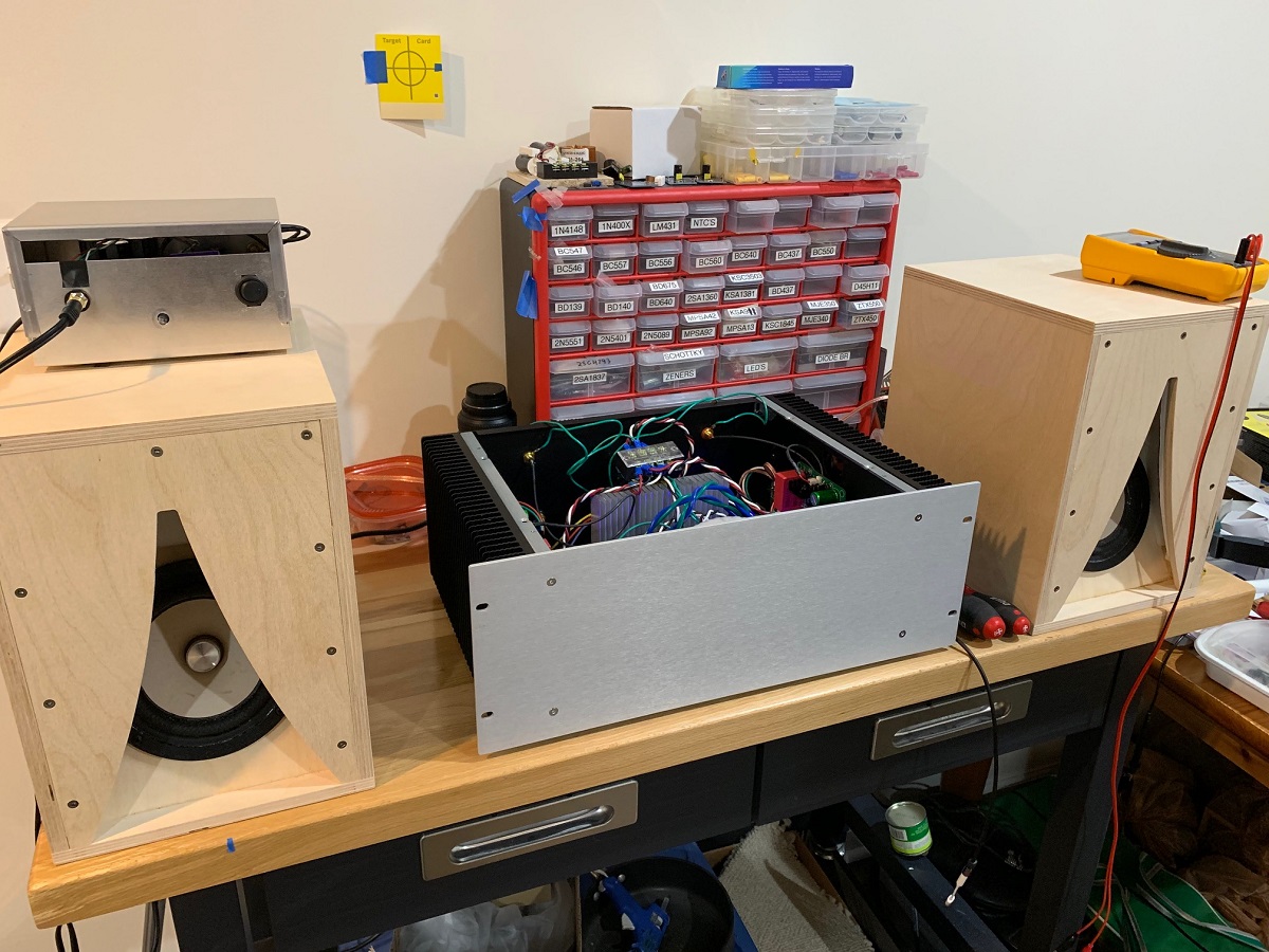
I have listened to about 3 songs so far on my W5-2143 XKi full range speakers. Very nice sound - deep powerful bass. Will debug the ground loop some more but about time to stop anyhow as it is past 4AM here. Here is a shot of the amp with the speakers on my test bench:
Great news is that the design and layout are all good. Never have I fired up such a big amp (600VA trafo and 40+w in SE Class A) so uneventfully. Although precautions were taken such as having multiple DVM's connected to test probe leads across the source resistors to monitor current, and also let it burn in for 10 minutes while standing far away to make sure none of the electrolytics blow, should I have made a mistake in installing them.
So the amp is pretty much at steady state temperature and suprisingly, the 4U x 300mm heatsink can work here: I am getting 58C (just a tad over the usual 'allowable' 55C) at the hottest points near the ends of the heatsink. 52C at the middle of theatsink and 72C at the top of the snubber boards where the MOSFETs are. This means that a 4U x 400mm will run very comfortably.
I am running +28.3v and -28.6v at 1.65A for 94w of dissipation per channel. This is with the top lid off.
Alison Kraus & Union Station sounds great. 😀
Great news to report is that the Alpha Nirvana fired right up with no issues and not a single adjustment! I have a 22R resistor placed in the PCB header socket (per the simulation) and DC offsets are 5mV on left channel and 3mV on right channel. Quiescent bias current is 1.65A with +28.3v and -28.6v rails under load provided via an Antek AN-6224. PSU is a single SLB. It is playing music now and with nothing connected, I was getting 0.2mV rms noise at the speakers. Connecting my iPhone with 3.5mm to RCA cable is generating a small amount of hum - ground loop I think. I am running the speaker negative from the amp PCB. I think moving the speaker return to the SLB might help.
Here are the snubber board with the Fairchild MOSFETs mounted:
Here is the amp board mounted in a DIYA Store/Modushop 4Ux300mm Dissipante case with UMS heatsinks. The PCB mounts perfectly to the 4 standoffs. I mounted the MOSFETs pretty far away near the edges.
Another view showing the SLB and SLB heatsink. The trafo is mounted towards the front and standing on edge to have enough room.
I have listened to about 3 songs so far on my W5-2143 XKi full range speakers. Very nice sound - deep powerful bass. Will debug the ground loop some more but about time to stop anyhow as it is past 4AM here. Here is a shot of the amp with the speakers on my test bench:
Great news is that the design and layout are all good. Never have I fired up such a big amp (600VA trafo and 40+w in SE Class A) so uneventfully. Although precautions were taken such as having multiple DVM's connected to test probe leads across the source resistors to monitor current, and also let it burn in for 10 minutes while standing far away to make sure none of the electrolytics blow, should I have made a mistake in installing them.
So the amp is pretty much at steady state temperature and suprisingly, the 4U x 300mm heatsink can work here: I am getting 58C (just a tad over the usual 'allowable' 55C) at the hottest points near the ends of the heatsink. 52C at the middle of theatsink and 72C at the top of the snubber boards where the MOSFETs are. This means that a 4U x 400mm will run very comfortably.
I am running +28.3v and -28.6v at 1.65A for 94w of dissipation per channel. This is with the top lid off.
Alison Kraus & Union Station sounds great. 😀
Attachments


Last edited:
I am more than relieved - thanks X!
A lot of work behind all this, particularly as you have SLBs on both channels, lots of electronics to make that work. Beautiful output devices with jockey pcbs for snubbers.
The next step will be to lie back and listen to it. I expect this to sound very than the BB, to be perfectly honest. It has a more direct drive from input to speaker......
Thanks so much for the hard work and the terrific photos. We all feel we are there........
Hugh
Thank you, Hugh - your design is awesome, as usual. And huge thanks to JPS64 for another superb layout. 
This amp is so amazingly compact for what it is: a 40w+ SE Class A operating from modest rails and a conventional chassis. This will make it a lot more approachable for those not wanting to play around woith CPU coolers and fans.
Playing some Blue Oyster Cult, then Van Halen, now... very enjoyable. I need to get to bed though - a work day in 4 hrs.
Well done X, I know you were probably in a hurry to get the build done and congratulations on having it play without any problems.
Now just imagine how good the amp would look when you get around to tidying up the internal wiring (not criticising , but that is just me, I like a tidy chassis)
Do you ever get a good night's sleep?
Well done to all involved especially Hugh here in Melbourne. he has not left himself much room to improve it seems.
Cheers,
Gary..
No Cpu coolers and noisy fans.........sounds like a plan!
I like the fact that those power mosfets can be remotely secured to any part of the heatsinks for optimum heat dissipation.
Love the diy speakers of yours.
I like the fact that those power mosfets can be remotely secured to any part of the heatsinks for optimum heat dissipation.
Love the diy speakers of yours.
Great work X. I agree, a 4U/400 will be better all around especially if someone wants to use dual SLB's, single large donut and optimum cooling all around. I was/am a still little nervous about the MOSFETs with flying leads (due to a propensity for oscillation), but it looks like there are safety features built in for that. More testing will show for sure, thanks for all your efforts!
Best,
Anand.
Best,
Anand.
- Home
- Amplifiers
- Solid State
- Alpha Nirvana 39w 8ohm Class A Amp