A project on my list is to add a sync input to a quality oscillator like Viktor's in order to provide truly synchronous analysis. Using synchronous averaging is a helpful start to reducing noise, but it does not address oscillator drift and you still need to use a windowing function. With an analog generator locked to the FFT analyzer, you can get rid of the window function and also use an FFT size that is optimal only for the ADC hardware, and not also the oscillator drift.
There's an article called 'Injection-lock a Wien-bridge oscillator' from Glen Brisebois of Linear Technology in the October 2012 issue of EDN. He goes into a good bit of detail about how to lock an oscillator, and the long and short is that you can inject a small amount of the sync signal into the oscillator's feedback loop and the quality oscillator will lock to the injected signal. So, you get the distortion properties of the analog oscillator while being able to lock the oscillator frequency to an external clock.
Practically, this can be used with an AP nicely: the AP can provide a DAC generated sine wave that is inherently locked to the system sample rate, and this signal will then be able to be injected into an external analog oscillator to lock it to the AP's sample clock, making it synchronous to the FFT analyzer. This principle probably also applies to many soundcard type analyzers, since the generator and analyzer will usually share the same sample clock.
I think the details of this are little more than adding a jack to an oscillator board and an attenuator, and maybe a little filtering, but I don't have an external oscillator to use for this purpose, so I have not experimented with this. Perhaps someone on this thread will want to take a stab at it?
I spent weeks of spare time on this. Even adding an isolation transformer. Still the distortion increase was significant. I'm ready to go back at it but need a fresh take on the process.
I spent weeks of spare time on this. Even adding an isolation transformer. Still the distortion increase was significant. I'm ready to go back at it but need a fresh take on the process.
What level did it take to lock in?
Its been years but I remember it was millivolts. I think something about how I connected to the feedback may have impacted it when an external source was connected.
If I can find the notes its worth a review and retry.
If I can find the notes its worth a review and retry.
I spent weeks of spare time on this. Even adding an isolation transformer. Still the distortion increase was significant. I'm ready to go back at it but need a fresh take on the process.
Was it the injection signal that was disturbing the oscillator in a particular way that was causing distortion? I assume that the injection signal itself would at least have to be very low in distortion itself. Also, there might be a mechanism at work that causes distortion just as a result of pulling the oscillator frequency a bit. Might the distortion be a function of how much the oscillator was being pulled?
I would have guessed that the best approach to pulling the oscillator to the exact desired frequency would be to use a PLL. This is very straightforward with a state variable oscillator, but a little less straightforward with a Wein bridge oscillator. If only pulling it a little bit, a JFET VCR could probably be used to tweak one of the tuning resistors to pull the frequency a little bit.
Pulling the frequency of a state variable notch filter is the approach used for autotune in many analog THD analyzers.
Victor's oscillator has remarkably low distortion, and it would be interesting to see if a state variable oscillator could perform as well if it was designed and implemented with the same amount of care and expertise.
Cheers,
Bob
Hm, I thought SilentSwitcher doesn't have galvanic isolation from USB
It does when powered from a Powerbank. Which is recommended for sensitive uses. I always have a few charged Powerbanks at hand ;-)
Jan
Thanks Demian. My experience is that where you inject the signal is critical and I expect it to be a critical issue between level and the amount of frequency pull required.
I suspect there is a very nonlinear cosine shaped relationship between pull amount and distortion.
My distortion reduction technique as mentioned before is to use an oscillator topology set just below oscillation as a filter for the same topology in critical-ish oscillation. Matching of the frequency networks is of course critical when the oscillator is analog. When it is digital I can get decent cleanup and frequency stability.
I have not done a direct comparison between frequency locking and filtering to compare distortion. I do know level stability can be significantly better with the filter approach as it allows a lot less critical level control or even fixed crystal like references.
The other advantage of the filter approach is that you can deliberately lock harmonic oscillators for additional wave shaping or distortion reduction.
I think the limit is still the active components and then the capacitors.
Using lock in amplifiers it is possible to measure harmonics 160 dB below the fundamental. Just to drive folks nuts the amplifiers can be DSP based!
Last edited:

FWIW --- The ShibaSoku 725D uses IIRC 3 notch filters . (0 = -100db)
View attachment 786992
THx-RNMarsh
The VP7722A distributed under Panasonic brand uses 2 notch filters. Can be found on e-Bay etal for about 1200 USD. Same basic topology as ShibaSoku 725D
Dropbox - Panasonic VP-7722 service manual.pdf - Simplify your life
Either will help with ultra-low distortion generator development. Note -The VP7722 has built in generators (THD and IM). Easily beats its specs.
Both analyzers can be used with external FFT on the residual port provided and get much lower distortion readings.
THx-RNMarsh
Last edited:
Very interesting and very impressive, Richard. Whose oscillator is the source?
Can you advise applied signal amplitude? I'd like to try to estimate noise density of the system referred to input. Maybe that's detailed in the manual somewhere...
Many thanks.
Can you advise applied signal amplitude? I'd like to try to estimate noise density of the system referred to input. Maybe that's detailed in the manual somewhere...
Many thanks.
Khron-Hite 4402B at 1v > 1K load
[I modified it for lower distortion]
Davada's gen design is significantly better-->

Some clocking/timing signal cross-talk is seen.... not from gen. From analyzer.
THx-Richard
[I modified it for lower distortion]
Davada's gen design is significantly better-->
Some clocking/timing signal cross-talk is seen.... not from gen. From analyzer.
THx-Richard
Last edited:
here is KH 4402B with a passive notch at 2H... to cancel out the 2H
can do same for 3H. Just a crude proof of concept's effectiveness. Modest notch depth.
if you notch out 2H and 3H... pretty much for most gen = zero HD
🙂 Maybe a tracking notch to remove residual harmonics from a variable freq low distortion generator.??

2 years ago.
THx-RNMarsh
can do same for 3H. Just a crude proof of concept's effectiveness. Modest notch depth.
if you notch out 2H and 3H... pretty much for most gen = zero HD
🙂 Maybe a tracking notch to remove residual harmonics from a variable freq low distortion generator.??
2 years ago.
THx-RNMarsh
Last edited:
Gossip from the lab
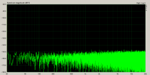
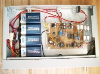
I needed a good case for my oscillator. I found it and slaughtered a $1500 Nokia Crypto VPN router. Good enough for my little oscillator. The first screenshot shows the switched off oscillator (everything below approx. -150dB). The second screenshot shows the switched on oscillator (battery powered) with the 1st harmonic, which dances around -145dBc. I need a better ADC. As you know, you are never satisfied yourself. Any recommendations?
I needed a good case for my oscillator. I found it and slaughtered a $1500 Nokia Crypto VPN router. Good enough for my little oscillator. The first screenshot shows the switched off oscillator (everything below approx. -150dB). The second screenshot shows the switched on oscillator (battery powered) with the 1st harmonic, which dances around -145dBc. I need a better ADC. As you know, you are never satisfied yourself. Any recommendations?
Attachments
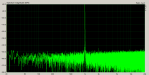

Very good question.What is the max amplitude of the signal (dbFS)?
What is the amplitude of the fundamental frequency in this measurement? We can't see the full graph.
If you really can measure such low harmonics directly on the ADC, then this sound card is unique. I have never seen residual harmonics below -130 dB when the best ADC chips was used. Xonar DX uses CS5361 ... According to the specification, this is not the best ADC chip....The second screenshot shows the switched on oscillator (battery powered) with the 1st harmonic, which dances around -145dBc. I need a better ADC. As you know, you are never satisfied yourself. Any recommendations?
- Home
- Design & Build
- Equipment & Tools
- Low-distortion Audio-range Oscillator