True, but it appears from the .asc file attached to post 13 we are seeing results of hardware testing with 22R stopper resistors in the output transistor bases instead of the 2R2 suggested in post 2.
Maybe the current source for VAS is not stable. Put a 1nF cap cross C E of Q16 to see if it fixes.
whatever other issues you may have, the whistle stopper resistors in the output device bases should be 2.2 Ohms, not 22 Ohms.
Okay, I'll try a quick input filter on the square wave before it goes into the 2.2 uF coupling cap to the input and see if that changes anything.You need an RC input filter for example 100R and 1nF.
You would want to see how such might affect the shape of the square wave before advancing further. There will be some inevitable rounding of the corners.
Okay, will report back.That's the wrong way to go. Don't slow down the amp. Slow down the input signal.
Jan
I need to see if at my job they have any 2.2 or 2 ohm resistors. Also, I'm back at school to finish off master's this Monday, so I can check there as well.True, but it appears from the .asc file attached to post 13 we are seeing results of hardware testing with 22R stopper resistors in the output transistor bases instead of the 2R2 suggested in post 2.
Will take a look at this after base stoppers changed and filtering input signal.Maybe the current source for VAS is not stable. Put a 1nF cap cross C E of Q16 to see if it fixes.
Will report back. Thanks.whatever other issues you may have, the whistle stopper resistors in the output device bases should be 2.2 Ohms, not 22 Ohms.
Input filter
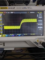
I added an input filter of a 10k in series with a 100 pF shunted to ground, fc of about ~160k.
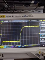
Here are the pics of the square wave response. This is no load.
When I turn on amp and have nothing on input/load (other than oscilloscope), I see the 8 MHz oscillation, that's still present.
I added an input filter of a 10k in series with a 100 pF shunted to ground, fc of about ~160k.
Here are the pics of the square wave response. This is no load.
When I turn on amp and have nothing on input/load (other than oscilloscope), I see the 8 MHz oscillation, that's still present.
Attachments

I added an input filter of a 10k in series with a 100 pF shunted to ground, fc of about ~160k.
Here are the pics of the square wave response. This is no load.
When I turn on amp and have nothing on input/load (other than oscilloscope), I see the 8 MHz oscillation, that's still present.
There is still a problem due to the 22R stopper resistors and the diffusion capacitance between the base and emitter of the output transistors acting as a low pass filter.
As a general rule a dominant pole created by Miller capacitor in the Vas needs to be at least 10 times more effective than any others present in the circuit.
That makes a compelling case to reduce the stopper resistor values to 2R2.
With RC values of 100R series and 1nF the output impedance of whatever source would be in series with 100R.
Low impedance creates less noise and is less susceptible to influence by sources of interference.
I see. So the 100 pF across the VAS is fighting with a pole that the base stoppers 22||22 ohm + output transistor capacitances is creating.There is still a problem due to the 22R stopper resistors and the diffusion capacitance between the base and emitter of the output transistors acting as a low pass filter.
As a general rule a dominant pole created by Miller capacitor in the Vas needs to be at least 10 times more effective than any others present in the circuit.
That makes a compelling case to reduce the stopper resistor values to 2R2.
With RC values of 100R series and 1nF the output impedance of whatever source would be in series with 100R.
Low impedance creates less noise and is less susceptible to influence by sources of interference.
I'll pick up some 1 nF caps, don't have any on me right now, that's why I had to resort to 10k + 100 pF.
With 30 volt supply rails you can fit series fuses for protection and rely on a single NPN/PNP output pair without the stopper resistors.
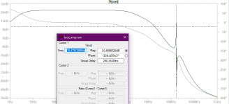
Just simulated again, just a normal AC simulation, looking at output after the zobel network.
Just noticed the big spike at 16 MHz which I'm seeing in real life on the scope.
Picture attached.
EDIT: when I change R14 from 2.2k to 10k, the 16 MHz peaking disappears.
Could R14 be the culprit of this oscillation?
500 diminishes peaking
5k diminishes peaking
10k diminishes peaking
Just noticed the big spike at 16 MHz which I'm seeing in real life on the scope.
Picture attached.
EDIT: when I change R14 from 2.2k to 10k, the 16 MHz peaking disappears.
Could R14 be the culprit of this oscillation?
500 diminishes peaking
5k diminishes peaking
10k diminishes peaking
Attachments
Last edited:
Also leave the Miller capacitor value at 100 pF. You have a 1n4148 diode in parallel with this - I suggest you remove it.
Just added another 2.2k resistor in series with R14 to ground. R14 is 4.2k now, 16 MHz oscillation still present at output, seems cleaner though.
EDIT: I notice when I turn down VAS Ic, the 16 MHz hump starts to get smaller.
EDIT: I notice when I turn down VAS Ic, the 16 MHz hump starts to get smaller.
Last edited:
Just added another 2.2k resistor in series with R14 to ground. R14 is 4.2k now, 16 MHz oscillation still present at output, seems cleaner though.
EDIT: I notice when I turn down VAS Ic, the 16 MHz hump starts to get smaller.
Replace current source circuit with an ideal current source. If that fixes the issue, the culprit is your current source.
Hmm... Good point. This might be it.Replace current source circuit with an ideal current source. If that fixes the issue, the culprit is your current source.
EDIT: In simulation, if I put a 1 nF across CE of Q16, hump goes completely away. This might be my issue.
EDIT2: I have a realistic value of 0.1 uF, going to try that. Looks good in sim.
EDIT3: I soldered the 0.1 uF ceramic type cap between the C node of Q16 and the E node (or V+ rail), and in practice it didn't seem to affect the oscillation at all :/
Attachments
Last edited:
Set the quiescent current to greater than 0 ma (about 100 ma) and the ringing should stop.
Or, reduce resistance R19 to 4.7 ohm, this should reduce ringing.
Or, reduce resistance R19 to 4.7 ohm, this should reduce ringing.
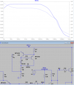
Square Wave Simulation
I found a some errors in the .asc file in the constant current source connections and made some back-to-basics simplifications in these structures.
I have set up the attached file to run with a link to Bob Cordell's website. I have not spent a lot of time on this so it is not perfect. I am posting it for anyone interested working on that.
Reference V(out) and V(nfb-) using the visible traces tool.
Attachments
Another guess is that you have right hand-plane zero in the system. From your plot, around 10MHz, the roll-off slop does not change much, but phase margin drops rapidly.
If that is the case. Put a 1K resistor in series of miller cap.
If that is the case. Put a 1K resistor in series of miller cap.
Last edited:
Just added another 2.2k resistor in series with R14 to ground. R14 is 4.2k now, 16 MHz oscillation still present at output, seems cleaner though.
EDIT: I notice when I turn down VAS Ic, the 16 MHz hump starts to get smaller.
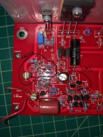
Can you post some images of the insides of your hardware that we might see if this provides any clues.
I took a look at your sim, looks good, I see the same decrease in 16 MHz hump as I do in my sims with adding the capacitor, which unfortunately didn't solve any real life problem.I found a some errors in the .asc file in the constant current source connections and made some back-to-basics simplifications in these structures.
I have set up the attached file to run with a link to Bob Cordell's website. I have not spent a lot of time on this so it is not perfect. I am posting it for anyone interested working on that.
Reference V(out) and V(nfb-) using the visible traces tool.
I will take a look at this in a few hours, thanks.Another guess is that you have right hand-plane zero in the system. From your plot, around 10MHz, the roll-off slop does not change much, but phase margin drops rapidly.
If that is the case. Put a 1K resistor in series of miller cap.
EDIT: In simulation, adding a 1k resistor in series with miller cap adds a massive spike at 10.1 MHz.
Will edit this post.Can you post some images of the insides of your hardware that we might see if this provides any clues.
The component references on the physical board are not the same as the ones in the schematic FYI.
Attachments
Last edited:
From this shot it appears the heat sink is not connected to earth - I suspected that might so. The best way to sort that is to put everything in a chassis and establish a proper earth system for the electronics.
It was my understanding that while earthing the heatsink within a chassis is a necessary safety practice (also necessary while prototyping in a higher voltage environment), troubleshooting the amplifier before mounting everything in a chassis was the correct approach.From this shot it appears the heat sink is not connected to earth - I suspected that might so. The best way to sort that is to put everything in a chassis and establish a proper earth system for the electronics.
Do you think earthing the heatsink will solve my oscillation problem?
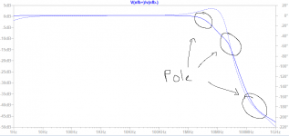
EDIT: I've attached a plot for gain and phase margin, a little unsure if that hump of phase is bad / how it affects reading off the phase/gain margin.
Also, am I correct in saying those rolloff points are poles?
16 MHz lies on -9.57 dB of the bode plot, is this my feedback factor? 22k / 1.2k?
Attachments
Last edited:
- Home
- Amplifiers
- Solid State
- Is this too much ringing?