Hmm... Maybe I was a little quick to jump the gun on the celebration.
The response looks really good with no load I guess, but with the load, you're right the response still has that ringing in it. Hmm...
when you have ringing at high power level test and do not have it at low level test, you might have forgot to put in a LPF at the amp input to prevent the amp being driven into slew limiting.
Function generators can put out square wave having very steep edges that, depending on signal amplitude, exceeds the maximum rate of voltage transition you amp is capable of following, causing VAS to saturate, or slew limiting. Slew limiting is one of the mechanisms ringing showing up in square wave response (in a feedback amp). You might want to insert a 1K resistor in series with the input cap, and replace the 33pF cap at the base of the input transistor with 470pF, and see if that makes difference, to at least confirm or rule out slew limiting.
Just a thought.
By the way, what type of output inductor are you using? your layout suggests it is a ferrite core SMD. In audio power amp the most commonly recommended is an air core coil.
There was no input filter for the image attached to post 1 the slope of which is just as steep now as it was then so no input filter.
The image attached to post 52 shows some slope - so one step forward but no magic bullet so we will just reset and forget - despite the fact an LPF on the input has been suggested and endorsed by contributors to the discussion.
That sort of approach leaves anyone wanting to help having to second guess what is going on when the goalposts keep moving.
Okay, I'll re-investigate the CCS configuration. I guess, if it's ripple prone, I should definitely implement an RC filter before on the rails.So we are back to square one. sgrossklass made pertinent comments in post 6 about the CCS operating current and the type of transistors used.
He described the LTP CCS as weird.
It is a pity this point was not explored earlier because any ripple on your positive supply has free entry via Q10 emitter to base junction - all because of a mistake in placement of the stopper resistors.
As it stands Q10 is not going to drive Q7 in any linear fashion and with Q8 constituting some form of collector load on Q10 you have the structure of an common emitter amplifier where the output is inverted with respect to the input.
The purpose of C10 is to serve as a corrective bootstrap. It will do that in a conventional CCS but here it will put supply rail ripple into the base of Q7.
So how is that going to cancel the impact of ripple entering via Q10 emitter base junction.
Will take a look at this in a second.I have drawn an .asc file along the lines used by Jung in the AudioXpress article with amendments in September 2007 with line rejection of 140dB.
His choice was for 2SA1016 transistors (150 V types) which he rated above MPSA56 general types used by Self which have 3 times or more capacitance at Vcb=10V.
The supply rail was +18V.
The test set up involved two voltage inputs in series Vin AC of 1Vrms and +18Vdc. The CCS loading was 1R. The result is measured between 1R and earth.
Hmm, when we solved the 16 MHz problem and I redid the test, I didn't have the input filter there, so I can try that again. Adding a 1k in series is easy, I'll try that and if it doesn't have any effect I'll also change the capacitance.when you have ringing at high power level test and do not have it at low level test, you might have forgot to put in a LPF at the amp input to prevent the amp being driven into slew limiting.
Function generators can put out square wave having very steep edges that, depending on signal amplitude, exceeds the maximum rate of voltage transition you amp is capable of following, causing VAS to saturate, or slew limiting. Slew limiting is one of the mechanisms ringing showing up in square wave response (in a feedback amp). You might want to insert a 1K resistor in series with the input cap, and replace the 33pF cap at the base of the input transistor with 470pF, and see if that makes difference, to at least confirm or rule out slew limiting.
Just a thought.
By the way, what type of output inductor are you using? your layout suggests it is a ferrite core SMD. In audio power amp the most commonly recommended is an air core coil.
Regarding the air coil, I knew I was going to get some flak about it. From what I understand, the issue is with a non air core inductor, when it saturates it induces distortion. I consulted my boss at work and he told me to choose an Iron Powder core type and then I specced the saturation current to be way higher than anything it would ever see, I think in this case it's 18 amps. So that's my reasoning, and I did it this way for completeness on the PCB end, as it's my first time doing the whole chassis, heatsink (had to learn how to drill and tap holes), etc. I just wanted to drop a component in instead of putting in two vias that I wasn't going to be certain how far apart they should be. But rest assured, I know the correct thing to do is use an wire-wound air core inductor, and next time I will be doing just that.
Will hook it up again with the input filter.There was no input filter for the image attached to post 1 the slope of which is just as steep now as it was then so no input filter.
The image attached to post 52 shows some slope - so one step forward but no magic bullet so we will just reset and forget - despite the fact an LPF on the input has been suggested and endorsed by contributors to the discussion.
That sort of approach leaves anyone wanting to help having to second guess what is going on when the goalposts keep moving.
Regarding the air coil, I knew I was going to get some flak about it. From what I understand, the issue is with a non air core inductor, when it saturates it induces distortion. I consulted my boss at work and he told me to choose an Iron Powder core type and then I specced the saturation current to be way higher than anything it would ever see, I think in this case it's 18 amps. So that's my reasoning, and I did it this way for completeness on the PCB end, as it's my first time doing the whole chassis, heatsink (had to learn how to drill and tap holes), etc. I just wanted to drop a component in instead of putting in two vias that I wasn't going to be certain how far apart they should be.
There are inductors in the LTSpice component library having 4uH inductance. Had you picked one of these for your simulation the symbol would have shown up on the .asc and the issues around this would have come to light earlier. Omitting to do so is not luce.
I'm sorry, I'm not following. Which issues would have come to light if I picked 4 uH inductance?There are inductors in the LTSpice component library having 4uH inductance. Had you picked one of these for your simulation the symbol would have shown up on the .asc and the issues around this would have come to light earlier. Omitting to do so is not luce.
EDIT:
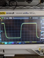
Here's the square wave with a 10 ohm load (blew up my 8 ohm dummy load) and the input slowed down.
10k R + 0.1 uF input filter, no series 1k to the input cap, and it seems to have gotten rid of the ringing with/without the load attached.
Attachments
Last edited:
Hi drinkingcube, that wave form doesn't look like the 10K-ohm - 0.1uF LPF is in working. 10K-0.1uF makes -3dB at 159 Hz and should have flattened your 10KHz square into almost a straight line with wiggles of a few mVp-p.
Hi drinkingcube, that wave form doesn't look like the 10K-ohm - 0.1uF LPF is in working. 10K-0.1uF makes -3dB at 159 Hz and should have flattened your 10KHz square into almost a straight line with wiggles of a few mVp-p.
Crap, sorry I think I remembered it wrong. I'm pretty sure it's the 100 pF from earlier. Let me check my post history.
Yeah, post 27, Is this too much ringing?
That's my mistake sorry
Yeah, post 27, Is this too much ringing?
That's my mistake sorry
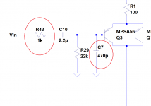
The LPF that you were given suggestion about looks like the R43 and C7 in the attached. Doesn't have to be 1k-470pF, can be other combinations with your available Rs and Cs as long as the product is around 0.47E-6, with R43 in the range of 100-2K ohm.
Attachments
I'm sorry, I'm not following. Which issues would have come to light if I picked 4 uH inductance?
EDIT:
Here's the square wave with a 10 ohm load (blew up my 8 ohm dummy load) and the input slowed down.
10k R + 0.1 uF input filter, no series 1k to the input cap, and it seems to have gotten rid of the ringing with/without the load attached.
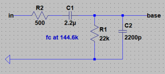
The higher the series resistance in a LPF the greater the noise. 100R + 1nF is to cover rf usually there would the impedance of a volume control with a direct feed in series with that so while the rf filter is too high for square wave 10kHz testing you would lower the -3 dB point so the rise time is increased and the settling time reduces.
4uH is the inductor value given in the circuit in your first post. There are two options for an .asc pick the inductor symbol on the menu bar or pick the component symbol two places to the right of that on the menu bar and look for ind or ind2 under Filter Products then pick a model from the library. There is an option to show the phase dot.
Anyway things have moved on from that. One thing I have noticed from the circuit board layout is you have routed the negative supply trace to the front end of your circuit between the connections of the output coil to the pcb.
You don't want any magnetic coupling effects getting into the amplifier via the supplies.
See attached pictures. Is the slight overshoot from the 60 ish degrees of phase margin or am I seeing it slew limit as the input square wave is overshooting as well.The LPF that you were given suggestion about looks like the R43 and C7 in the attached. Doesn't have to be 1k-470pF, can be other combinations with your available Rs and Cs as long as the product is around 0.47E-6, with R43 in the range of 100-2K ohm.
I see I see, sounds good.The higher the series resistance in a LPF the greater the noise. 100R + 1nF is to cover rf usually there would the impedance of a volume control with a direct feed in series with that so while the rf filter is too high for square wave 10kHz testing you would lower the -3 dB point so the rise time is increased and the settling time reduces.
4uH is the inductor value given in the circuit in your first post. There are two options for an .asc pick the inductor symbol on the menu bar or pick the component symbol two places to the right of that on the menu bar and look for ind or ind2 under Filter Products then pick a model from the library. There is an option to show the phase dot.
Anyway things have moved on from that. One thing I have noticed from the circuit board layout is you have routed the negative supply trace to the front end of your circuit between the connections of the output coil to the pcb.
You don't want any magnetic coupling effects getting into the amplifier via the supplies.
Attachments
This is quite a lot different from the image shown in post 105 - that was without any load on the output.
The peak-to-peak voltage is lower in the latest image and seemingly at the component level the LPF is the only thing you have changed.
The peaking looks like loss of high frequency gain (-12dB/Octave) within the amplifier.
The peak-to-peak voltage is lower in the latest image and seemingly at the component level the LPF is the only thing you have changed.
The peaking looks like loss of high frequency gain (-12dB/Octave) within the amplifier.
LPF has changed, Vpp levels have changed, response doesn't change much at all when I increase input levels.This is quite a lot different from the image shown in post 105 - that was without any load on the output.
The peak-to-peak voltage is lower in the latest image and seemingly at the component level the LPF is the only thing you have changed.
The peaking looks like loss of high frequency gain (-12dB/Octave) within the amplifier.
Post 105 had a 10 ohm load, and so did the picture you're commenting on in your post.
Don't make any changes to your Vas stage. There are other areas that have been commented on where there appears to have been no action.
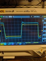
See attached pictures. Is the slight overshoot from the 60 ish degrees of phase margin or am I seeing it slew limit as the input square wave is overshooting as well.
With that input LPF and the signal amplitude there shouldn't be slew limiting. Since we are still seeing the ringing (that's now riding over the overshoot), we probably could bet on that it was not caused by slew limiting.
Was the input signal trace on the scope ahead of or after the LPF? If after, would you be able to probe it ahead of the LPF as well with a third channel of the scope?
Yes. It was scoped before the lpf. After I do my weekly 10 hours at work I can scope it.
Yes. It was scoped before the lpf. After I do my weekly 10 hours at work I can scope it.
If that is the case (that the blue trace in post #110 scope shot was probed off ahead of the LPF), which I hope not, then the ringing is more likely the result of the function generator interacting with its load than being generated by your amp --- your amp had been being fed with garbage to begin with.
By the way, I would replace or couble-up the 100uF C-ele across the Vbe multiplier with a 0.1uF ceramic or film cap. May not be related to our troubleshooting but for the heck of it.
Okay. Very interesting. I'll need to troubleshoot more specifically what is being fed to the amp.
What's the rationale for changing capacitance? Does 100uF make it less aggressive? Longer to charge up and adjust? Genuinely curious.
What's the rationale for changing capacitance? Does 100uF make it less aggressive? Longer to charge up and adjust? Genuinely curious.
The cap across the Vbe multiplier means to keep the impedance of the two nodes down at high frequencies, and a 0.1uF is more than what it takes. By using a large value electrolytic its ESL may or (may not) come into play at said high frequencies, possibly negating the purpose. Besides, a large capacitance could make the "Vbias pumping" effect, when the amp clips, more pronounced.
The cap across the Vbe multiplier means to keep the impedance of the two nodes down at high frequencies, and a 0.1uF is more than what it takes. By using a large value electrolytic its ESL may or (may not) come into play at said high frequencies, possibly negating the purpose. Besides, a large capacitance could make the "Vbias pumping" effect, when the amp clips, more pronounced.
There are two stages based around Q7 and Q11 that resemble a crude form of common emitter amplifier each in its' own peculiar and deplorable way.
- Home
- Amplifiers
- Solid State
- Is this too much ringing?