I mounted my Bridge rectifiers on the perforated base of the 4U case and they ran at nearly 80 celcius, they were then moved to the rear of the front panel using the pre drilled and tapped holes. They now run at 50 Celsius.
Hello, everyone. I am interested in M2x. It would be my almost first (made headamp before) serious diy amp. Have not a lot experience in making electronics. After first 10-20 pages of this threat did not found answers to folowing questions:
1. What is DC input to this amp? 24 V?
2. What power supply boards and schems should I use for amp? Can I use something from diy store?
3. What minimum transformer should be used with power supply bords? Output 2x24VAC and 2x300W?
4. What is recomended size for heatsink for one chanel? Is 300x100x50 enough? If
5. What internal size is recomended for amp case?
6. Is it realy hard to make this amp? I have found no step by step instruction. And a little bit afraid that I can face some questions I have no answers.
Sorry if my questions was answered somethere in this long threat. May I ask to answers to my questions in first posts of this threat? It would be good for everyone new to this amp design. 🙂
P.s. sorry for my english.
DC input? ...you mean rail voltage? about -+22VDC.
Trafo 2x22 VAC 400 VA should do it for both channels.
You can use universal PSU PCB from DIY Store for the power supply.
For chassis you can use e.g. DeLuxe 4 unit chassis in DIY Store.
It is an easy amp to build. Just take care of the Edcor trafo and maybe shield it to get less hum pickup (many posts about this).
rather 2x18VAC (300AV minimum) transformer. After using the universal PCB with diyaudiostore it will give ca. +/- 23 V DC needed for M2X.
The transformer in my M2x is rated 300VA. It has two independent secondaries, each 18V (AC) @ 8.3 amps RMS.
My M2x uses the power supply circuit design by Nelson Pass, schematic in post #83 of this thread...... but I decided to purchase electrolytic capacitors rated for 35V (not 25V) just to have a little bit of extra safety margin.
I installed my M2x in an eBay chassis with two enormous heatsinks: each was 150 x 300 mm, with 50mm fins.
Among the many different chassis sold by the diyAudio Store, the "Deluxe 4U" appears to be the best match to M2x, in my opinion.
I don't think 6L6 has made a build guide for this amp, but look at this great build documentary by ItsAllInMyHead
Bridge Rectifier Heat Sinking
Mark
Took some temp readings. The chunk of aluminum under the rectifiers is a bit smaller than I remembered. Aluminum measures 55 deg C at idle, 61 deg C with one channel loaded with 1KHz input at 10VRMS output into a 3.2 ohm power resistor load. I will probably substitute a larger piece of aluminum and use some arctic silver to see if I can get the temp down for longer term reliability.
It's hard to see in the photos, do you mount the rectifier diodes to the perforated floor plate? If so, does it provide enough heat sinking that the diodes run acceptably cool?
Mark
Took some temp readings. The chunk of aluminum under the rectifiers is a bit smaller than I remembered. Aluminum measures 55 deg C at idle, 61 deg C with one channel loaded with 1KHz input at 10VRMS output into a 3.2 ohm power resistor load. I will probably substitute a larger piece of aluminum and use some arctic silver to see if I can get the temp down for longer term reliability.
Attachments

Total investment in the empty chassis is under $100 including the $70 heat sinks.
...
Front panel was "brushed" with a belt sander.
Well done, cheers for ingenuity and thrift!

rather 2x18VAC (300AV minimum) transformer. After using the universal PCB with diyaudiostore it will give ca. +/- 23 V DC needed for M2X.
Yes, of course…..2x18 VAC......it is also what I used and about +- 23 VDC is also what I get.
I built mono blocks and used 500 VA in each amp.....in Deluxe 5U's. But this is way overkill and I did it because there was a lot of space and I like to "overkill". I also had in mind that maybe the chassis and PSU could be used for another amp board in the future running higher bias. There was a good offer on 2x18 V, 500 VA trafoes also…….Talema…..good stuff.
I will probably substitute a larger piece of aluminum and use some arctic silver to see if I can get the temp down for longer term reliability.
It could be that you have enough room to make the aluminum piece bigger, by extending it another 3cm North and also another 3cm South.
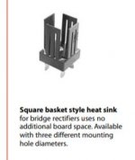
Also it might be possible to put one of these between each bridge and the aluminum:
An externally hosted image should be here but it was not working when we last tested it.
I didn't realize they made bridge rectifier heat sinks - and only a buck each - thanks for the tip!
I didn't realize they made bridge rectifier heat sinks - and only a buck each - thanks for the tip!
too small for my orientation
Attachments
I don't think 6L6 has made a build guide for this amp, but look at this great build documentary by ItsAllInMyHead
Thank you for the kind words. I haven't finished my posting over there just yet. I had promised to put up my full notes, and I've slacked off since finishing the amp and enjoying my first First Watt. I've got them pretty much done and in a format that should work for the forum. I'll commit to getting them up by EOW next week after the long weekend.
I hope it helps a few other noobs!
BTW - I just finished up an Aleph J, and I'm working on the SissySIT. Modularity goal, met. I've definitely caught the DIY bug. The M2x is a superb amp, IMO. I love leaving it alone for months and just listening, and the when I get an itch, I can swap a daughter card to see what I can learn. I am still gradually learning about electronics. I'm reading a ton on-line. Still, I make ridiculous errors. 😀
Do I understand correctly: the assembly of the rectifier bridges on the perforated mounting plate is insufficient to cool them?
I hope it helps a few other noobs!
I'm sure it will. Your candor will help encourage others, who may be on the fence, that they aren't alone and this can be done. One step at a time.
BTW - I just finished up an Aleph J, and I'm working on the SissySIT. Modularity goal, met. I've definitely caught the DIY bug.
I'd say so! Hmmm, that sounded vaguely familiar... Perhaps from earlier in this thread...
... other First Watt amplifiers. Which you will want to build when this one is done, see.
😀
Let this be a lesson to others, betcha can't build just one.
Do I understand correctly: the assembly of the rectifier bridges on the perforated mounting plate is insufficient to cool them?
Hard to know for sure. In Batty's post #2461 he noted 80 deg C mounted to the perf plate. Since it is steel, it's not that great a heat sink. Some type of thermal compound might help.
The GBPC 35 series bridge rectifier data sheet ratings are at 55 deg C which implies a need to de-rate the device above that temp. But 35A is very conservative for this design. Data sheet also states a max diode junction operating temp of 150 deg C. Seems getting the bridge down to 55 deg C is a worthy goal.
Not sure if 6L6 or others are reading this and have also taken measurements and/or want to weigh in on the diyStore chassis sub plate adequacy as a heat sink for the bridges.
https://www.mouser.com/datasheet/2/308/GBPC3506-1301062.pdf
Do I understand correctly: the assembly of the rectifier bridges on the perforated mounting plate is insufficient to cool them?
I think mounting on the perforated plate is fine for the M2x and F5. Mine measure ~120F with an infrared thermometer and I can touch their sides. They feel warm - not hot.
Since reading the comments on rectifier cooling I've ordered an aluminium bar to bolt between the base plate and chassis, and a couple of these in case they turn out to be a better solution: Computer Cooler Radiator Aluminum Heatsink Heat sink Metal Rectifying Bridge Radiator KBPC Heat Sinks for Bridge Rectifier Diode-in Contactors from Home Improvement on Aliexpress.com | Alibaba Group
(So far, I haven't found a bolt long enough to allow me to use both!)
(So far, I haven't found a bolt long enough to allow me to use both!)
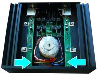
My M2x uses two GBPC3510 bridge rectifiers, mounted to the chassis floor with nothing more than a bolt and some heatsink grease. When I look at photos of the original First Watt M2 amplifiers that were built by Nelson Pass and sold to customers for real money, I think I see the same thing: GBPC bridges bolted to the chassis floor. (Blue arrows)
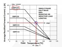
According to the First Watt user's manual on their website, the M2 amplifier draws less than 160 watts from the AC mains. Thus each of the two transformer secondaries delivers less than 80 watts. The secondaries are 18VAC (RMS) so the current in each secondary is less than (80 / 18) = 4.5 amperes (RMS).
Applying a very conservative 4X margin-of-safety, I'll check the datasheet's max allowed temperature when the bridge rectifier current is (4 times 4.5 amps). Namely, 18 amps.
The dataseet figure is shown below. At 18 amps average current, the bridge rectifier will be just fine if you keep its case temperature below about 95 degrees C. Of course it will be very happy if you keep its case temperature far, far below 95C. But it will thrive and prosper and meet its specifications even at 95C. Conservatively.
_
Attachments
- Home
- Amplifiers
- Pass Labs
- The diyAudio First Watt M2x