Solved the hum!
Sorry for the rapid fire posting (can you tell I'm excited?!), but I seem to have solved it.
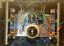
The ground from the L channel PCB (which, recall, has nothing landed to it) was passing right over the Antek torroid. I unplugged this from the SLB ground hub AND I moved both it and the L channel speaker ground as far away from the torroid as possible. They both still land on the SLB hub. This seems to have solved the hum issue.
Photo attached.
Wahoo! Thanks all for the quick help. Now I can nicely dress the cables 😀.
Sorry for the rapid fire posting (can you tell I'm excited?!), but I seem to have solved it.
The ground from the L channel PCB (which, recall, has nothing landed to it) was passing right over the Antek torroid. I unplugged this from the SLB ground hub AND I moved both it and the L channel speaker ground as far away from the torroid as possible. They both still land on the SLB hub. This seems to have solved the hum issue.
Photo attached.
Wahoo! Thanks all for the quick help. Now I can nicely dress the cables 😀.
Attachments
Sorry for the rapid fire posting (can you tell I'm excited?!), but I seem to have solved it.
Wahoo! Thanks all for the quick help. Now I can nicely dress the cables 😀.
Excellent work Metaphile!!
It’s very satisfying to tame the “HUM” beast, we’ve all been there 🙄
When you clean up all your wiring make sure to twist all of the AC wiring, primary and secondary side of the Trafo.
Enjoy your new F6!!

Nice work! Glad you got it fixed so quickly.
Enjoy the hum-free music.
Do twist the primary red/black wires when you get the chance. That will help too.
A hum free Aleph J by evanc and a hum free F6 by metaphile. 2 quiet Class A amps courtesy SLB in one day. That’s a pretty good day.
Enjoy the hum-free music.
Do twist the primary red/black wires when you get the chance. That will help too.
A hum free Aleph J by evanc and a hum free F6 by metaphile. 2 quiet Class A amps courtesy SLB in one day. That’s a pretty good day.
Last edited:
Nice work metaphile
You guys are making it easy to get great results. Plus I cheated by making mono amps.
You guys are making it easy to get great results. Plus I cheated by making mono amps.
Yes, monoblocks are usually easier to get silent. A lot of it still depends on good star grounding topology practice though.
Hello SLB looks promising. I have few questions.
1. The issue here below Tom mentioned is affect SLB? Supply Filtering and why Capacitance Multipliers are NOT the Answer
2. Is there any reason commercial amp pioneers such as (goldmund, accuphase, Pass, krell, MF, gryphon, burmester...) using mostly crc instead of cm or regulated ps. And many out there and i also hear that there is sonic improvement when they replace regulated ps with simple CRC. There must be something affect sound instead of ripple, i mean some smps have great ripple performance but not a common choice for amplifiers.
Thanks in advance.
For Class AB amps with a high intrinsic power supply ripple-rejection ratio (PSRR) a cap multiplier isn’t necessary as the amp takes care of the ripple induced hum. So using just a CRC provides the cost savings and a very low impedance current supply is presented to the amp.
For a pure Class A amp where the bias current runs at it maximum despite whether or not any music is playing, these amps have a well defined maximum current they need - it’s the same all the time. Many of these amps, including many single ended Class A, have no PSRR to speak of: that is, ANY ripple on the supply rail shows up as audio signal on the speaker. This is the ideal situation to use an SLB or “ripple eater” based power supply. The SLB provides the amp with the PSRR it lacked.
However, as Tomchr points out, the cap multiplier may be more prone to mains input voltage variations to induced hum. I haven’t experienced this with the SLB - but a good things that helps audio sound quality is a good UPS - it provides active mains voltage stabilization and cleans it up to remove spurious motor induced noise from heavy equipment connected to the mains. The UPS also does a very good job cleaning up EMI/RFi contamination of the mains.
The SLB is probably not needed for a typical Class AB amp with circa -70dB or better PSRR. But for most pure Class A amps we find on the forums around here, it does a great job of forcing convenience and ultra low ripple. 5A is the maximum current it was designed for and still run optimally. 5A is a lot of current and you won’t get hot rectifiers and their associate headroom loss using the SLB.
Rod explains some of the drawbacks of a Cap Mx here Capacitance Multiplier Power Supply Filter
Also, the Cap Mx in that tube amp uses a MOSFET, which Rod also touches upon in that article.
Also, the Cap Mx in that tube amp uses a MOSFET, which Rod also touches upon in that article.
Xrk,
Did you have a chance to try ideal bridge rectifier with SLB ps?
SLB is SMPS right?
What is the model of owon ossiloscope you used to measure 1mV ripple?
Did you have a chance to measure peak to peak ripple instead of rms?
Did you have a chance to try ideal bridge rectifier with SLB ps?
SLB is SMPS right?
What is the model of owon ossiloscope you used to measure 1mV ripple?
Did you have a chance to measure peak to peak ripple instead of rms?
SLB uses ideal bridge rectifier via LT4320 - that is the core of the SLB to give DC from AC secondaries of a linear transformer. The results presented are with a linear transformer not a SMPS.
SLB v2 (May 3, 2019) Production Board Top View:
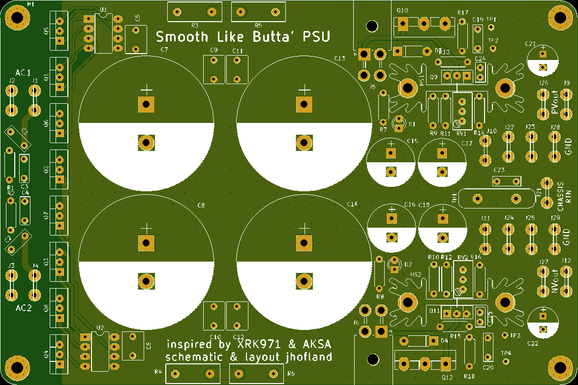
BOM (txt and csv format) and pdf schematic are below.
OK (and apologies if I missed the post), I can find the BoM for the dual rail board (above) but is there a posted BoM for the single rail unit somewhere? I might have missed the link in Post #1.
I know that there have been at least one variance from the dual rail BoM as per this:
So, it's not just a simple ... order half.Hey guys, we just discovered a small error with the orientation of Q5, the BD139 used in the SLB SR board. Pin 1 is denoted by the square pad, this will have the part’s front side in contact with heatsink if you use the large Fischer style heatsink. This part really doesn’t need such a large heatsink and a small sheet metal stamped or C channel aluminum one would work fine. Small heatsinks like that can be flipped around to the “back” of the BD139. Alternatively, one can mount a BD139 with its front towards the heatsink. Make sure you use a non conductive shoulder washer or bushing on the mounting screw to prevent it from contacting the metal pad on the back of the BD139.
My apologies for not catching this earlier - but should not be a problem as long as you mount the part with pin 1 on the square pad.
The SLB dual rail does not have this issue.
I'll go through the details myself but if there's an official BoM, that would save time. It's pretty easy to import the detail into octopart but avoidance of data handling errors is always preferred.
SLB Single Rail schematic and BOM on Post 145:
The SLB (Smooth Like Butter) Active Rect/CRC/Cap Mx Class A Power Supply GB
The SLB (Smooth Like Butter) Active Rect/CRC/Cap Mx Class A Power Supply GB
SLB Single Rail schematic and BOM on Post 145:
The SLB (Smooth Like Butter) Active Rect/CRC/Cap Mx Class A Power Supply GB
Magic. The thread search function doesn't work well with a three letter "word" like bom ..
I'm running a SLB SR with 22v AC transformer hoping to get 24v DC out.
At the big caps, I'm getting 32V. But no matter how I adjust the trim pot I can not get below 30V.
I think I have the new PCB with Q5 fixed.
Any hints?
At the big caps, I'm getting 32V. But no matter how I adjust the trim pot I can not get below 30V.
I think I have the new PCB with Q5 fixed.
Any hints?
You need to apply a real load. But adjustment range probably no more than 1v. I recall about 25v was as low as I got on M2X. It works fine and you get more headroom on the amp. There is a way to get more drop by changing resistors.
I'm running a SLB SR with 22v AC transformer hoping to get 24v DC out.
At the big caps, I'm getting 32V. But no matter how I adjust the trim pot I can not get below 30V.
Just make sure the BJT transistor is connected when you apply a load, if not all the current flows through a .5w resistor and POOF!!😉
Interesting comments on sound quality improvement with just using an LT4320 active bridge vs conventional bridge. This is for Prasi’s active bridge, but similar to one’s used here on SLB.
LT4320 based active rectifier
LT4320 based active rectifier
You need to apply a real load. But adjustment range probably no more than 1v. I recall about 25v was as low as I got on M2X. It works fine and you get more headroom on the amp. There is a way to get more drop by changing resistors.
I was following one of your earlier posts:
I have found through trial and error that the Antek 3222 (300VA) 22v provides about the right 24-25vdc rail under a 1.3A bias current load typically used on Pass 25w amp designs. This has been verified to work on my M2X as well as member SLk23’s M2X. Just one 300VA trafo is enough
The way to estimate the trafo rating is decide what voltage you want under load, say 24v. Add 3v for cap Mx dropout, add 5v for sag, so 24v +8v is 32v. Divide that by 1.4 and that’s the zero load rated AC voltage. 32/1.4=22.8v and so 22 is the closest one.
Is this always going to be a trial and error. Or once the voltage drop of a transformer under load is decided, we can compute the output voltage?
The trial and error is related to the actual voltage sag of the trafo under your specific load in amps. Antek is different than Talema, and that is different than Toroidy, etc. You can go by the transformer manufacturer's spec sheet, but that rarely gives the sag vs load. They will quote a minimum voltage at some load. Regarding the adjustment pot - I have found that going with about 3v drop (only adjustable circa 1v to 1.5v range) gives good performance of low ripple. In general, I have found that voltage sag under typical Class A loads is between 3 and 5v from un-loaded condition for Antek's. That's the thing with capacitance multipliers - they are mot voltage regulators, but voltage smoothing devices. You can't pick your exact voltage.
The trial and error is related to the actual voltage sag of the trafo under your specific load in amps. Antek is different than Talema, and that is different than Toroidy, etc. You can go by the transformer manufacturer's spec sheet, but that rarely gives the sag vs load. They will quote a minimum voltage at some load. Regarding the adjustment pot - I have found that going with about 3v drop (only adjustable circa 1v to 1.5v range) gives good performance of low ripple. In general, I have found that voltage sag under typical Class A loads is between 3 and 5v from un-loaded condition for Antek's. That's the thing with capacitance multipliers - they are mot voltage regulators, but voltage smoothing devices. You can't pick your exact voltage.
Understood, to add on top of that, I think my house voltage matters to as that affects the output of my transformer.
- Home
- Group Buys
- The SLB (Smooth Like Butter) Active Rect/CRC/Cap Mx Class A Power Supply GB