Jan, you are probably right/oscillator is good enough,
but we are all looking for perfection.
Anyway, it is fascinating to look into almost borders of that what is doable.
Isn't it the same with THD measurements to extremes?🙂
Yes, can't say I disagree ...
Jan
Just for fun, have made Victor,s 1kHz oscillator shielded with Cu-foil and measured again.
Drift is still present, but the whole histogram become more symmetrically.
Sure, change is quite small and probably not relevant for audio use, but is definite measurable,

and interesting to compare with unshielded measurement.
https://www.diyaudio.com/forums/attachment.php?attachmentid=773551&stc=1&d=1565287909
Drift is still present, but the whole histogram become more symmetrically.
Sure, change is quite small and probably not relevant for audio use, but is definite measurable,
and interesting to compare with unshielded measurement.
https://www.diyaudio.com/forums/attachment.php?attachmentid=773551&stc=1&d=1565287909
Attachments
Thanks Bob, clear. If the oscillator has phase noise, that then also causes phase noise about the harmonics, right? Does that matter as long as the bin width is larger than the frequency deviations?
Jan
Not speaking for Mr. Cordell...
If you consider "phase noise" to be frequency modulation of a tone (phase modulation would be similar), then the bandwidth of the harmonics would be that of the fundamental times the order of the harmonic. (Second harmonic being 2X, etc.)
And, if you go to the next thought, phase modulation of the conversion clock in a mixed signal system - like an audio DAC - effectively phase modulates all the tones at the output of the device. After all, a DAC is essentially a frequency multiplier aka mixer (in the RF sense, not the pro audio engineer sense).
Taking the next step with regard to an audio system, that implies that the musical information is phase modulated. Isn't this like moving a loudspeaker back and forth relative to the listener?
How much of this might audible and in what way is a really good question. After all, people are constantly moving their heads when listening to music, whether they want to or not. From what I've read, subtle head movements are part of the brain's overall system to localize sound.
Getting back to testing and audio oscillators, I think this is why using averaging to test a device can be misleading. Yeah, it allows you to dig deeper into the noise floor because while the signal itself is assumed to be constant over a lot of sweeps that allow for the averaging, the noise is assumed not to be. Thus, the noise largely gets averaged down.
However, if the noise is really chaotic with a small number of events that are really large and the rest very small, the large events get averaged down to almost nothing, too. But, they could be really significant in terms of listening. (This kind of thing is a consideration in measuring communications systems with a spectrum analyzer and internal demodulator. One symbol, which represents a number of bits, might be awful, but when averaged in with several hundred others, the overall effect is barely measurable in terms of dB. Those bits are still lost.) This may be a real consideration in terms of your observation about the size of FFT bins and the effect this has on measurements. Dunno, personally.
Very interesting!Just for fun, have made Victor,s 1kHz oscillator shielded with Cu-foil and measured again.
Drift is still present, but the whole histogram become more symmetrically.
Sure, change is quite small and probably not relevant for audio use, but is definite measurable,
View attachment 773547
and interesting to compare with unshielded measurement.
https://www.diyaudio.com/forums/att...on-audio-range-oscillator-1khz-unshielded-pngView attachment 773551
Any idea how much of this was thermal in nature? By thermal, I mean small changes caused by air movement. It might not be electrical shielding making the difference, but rather control of the air currents across the components. Or, it really could be electrical shielding. Or, both. Or, keeping the leprechauns out.
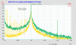
This is my take at measuring Victor's oscillator.
The measurement chain is Victor's (1Vrms out) -> massive-parallel buffer (8 X LM4562, 50 ohm output impedance) -> notch filter -> 60dB LNA -> audio interface.
The spectrum in the attachment shows the 2nd harmonic only at a level of -98dB w.r.t. 5Vrms (audio interface range). Correcting for the notch filter attenuation of 12dB@2kHz, and the LNA gain of 60dB, the 2nd is at -146dB w.r.t. 5Vrms, i.e. at -136dB w.r.t. 1Vrms.
Assuming now that the 3rd harmonic is just below the noise, i.e. at -103dB, and performing the calculation with the 3rd attenuation of 8dB in the filter, it would amount to -145dB w.r.t. 1Vrms.
Sorry about the mains interference, but it does not influence the above results.
Regards,
Braca
Indicates HUM pickup do not shielding...😀
Just for fun, have made Victor,s 1kHz oscillator shielded with Cu-foil and measured again.
Drift is still present, but the whole histogram become more symmetrically.
Sure, change is quite small and probably not relevant for audio use, but is definite measurable,
View attachment 773547
and interesting to compare with unshielded measurement.
https://www.diyaudio.com/forums/att...on-audio-range-oscillator-1khz-unshielded-pngView attachment 773551
Hmm, looks like hum modulation, but side freq. are not hum freq. related..
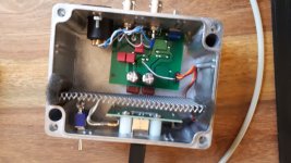
I learned from the victor's LDO:
1. has to be boxed completely 😱
2. the used LME op-amp may have some pop noise, do the substrate defect,
as my first op-map had this issue
Look at my pictures... 😀
BTW: connected the LDO as balanced
Hp
Attachments
may the new TO op-amp OPA1656 as a replacement or better choice ??
OPA1656: High-Performance CMOS Audio Op Amp
OPA1656: High-Performance CMOS Audio Op Amp
This brings up (the admittedly off topic topic of) PCB layout and design, and I'm convinced (from my informal studies of human factors) that one should make EVERY effort to make component placement and orientation consistent. Have all BJTs facing the same way, have pin 1 of all chips in the same direction, etc. The only exceptions would involve microwave frequencies, where an extra half inch of trace length really makes a difference.😀
Yes similar happens to all of us one day or another. And once I even managed to insert 4 TO92's in a row with the same orientation, except that one was rotated on the board....
I now routinely check pinout once I receive the PCB. Takes a minute at most, can save a lot of aggravation (and $$).
Jan

In case of "hand picked" components, it does make sense.
That's what silkscreen is for 🙂
#off-topic
Nobody is perfect. I know what can happen in a "hand picked" factory, despite a silkscreen.
(In a factory of Text Lite Ltd, Limerick, Ireland. Women with a grade in literature or so were working there)
Nobody is perfect. I know what can happen in a "hand picked" factory, despite a silkscreen.
(In a factory of Text Lite Ltd, Limerick, Ireland. Women with a grade in literature or so were working there)
Last edited:
Hum is some larger, than I think it could be ok (for battery powered device). You can try cable with better shield. I use diy-cables made from fine quality RG58, RG59 (or analogs) and have lower hum.Look at my pictures... 😀
Thanks for comments
I haven't done any further investigation, but change is clearly visible and repeatable, no doubt about that.
Just es i said before, the whole change is on extremely low scale and probably of no real meaning for audio purpose.
I am more concerned for oscillator stability and accuracy - every time when is it switched on, about 20min. is needed till mean frequency is achieved, but this frequency is always different - a few Hz more or less than 1kHz.
The question is: if that few Hz have impact et all on THD measurements or not?
All that what i have said, by any mean does not imply that oscillator have some strange behavior or error.
I have only look at it from "high frequency" perspective, once more-is that important for audio- i simply don't know?
Very interesting!
Any idea how much of this was thermal in nature? By thermal, I mean small changes caused by air movement. It might not be electrical shielding making the difference, but rather control of the air currents across the components. Or, it really could be electrical shielding. Or, both. Or, keeping the leprechauns out.
The oscillator was already in metal box together with 4x9V battery, i have made only extra tight shielding of circuit board itself.Hmm, looks like hum modulation, but side freq. are not hum freq. related..
I learned from the victor's LDO:
1. has to be boxed completely 😱
2. the used LME op-amp may have some pop noise, do the substrate defect,
as my first op-map had this issue
Look at my pictures... 😀
BTW: connected the LDO as balanced
Hp
I haven't done any further investigation, but change is clearly visible and repeatable, no doubt about that.
Just es i said before, the whole change is on extremely low scale and probably of no real meaning for audio purpose.
I am more concerned for oscillator stability and accuracy - every time when is it switched on, about 20min. is needed till mean frequency is achieved, but this frequency is always different - a few Hz more or less than 1kHz.
The question is: if that few Hz have impact et all on THD measurements or not?
All that what i have said, by any mean does not imply that oscillator have some strange behavior or error.
I have only look at it from "high frequency" perspective, once more-is that important for audio- i simply don't know?
This brings up (the admittedly off topic topic of) PCB layout and design, and I'm convinced (from my informal studies of human factors) that one should make EVERY effort to make component placement and orientation consistent. Have all BJTs facing the same way, have pin 1 of all chips in the same direction, etc.
I know a friend who is an audio designer/manufacturer, he does that too. I can't accept that because it inevitably will compromise performance.
Jan
#off-topc
(BTW, I was talking about non-audio applications like the PX-1000)
Cheers, E.
There are always exceptions, but, as you know, they also prove the rule. 😉I know a friend who is an audio designer/manufacturer, he does that too. I can't accept that because it inevitably will compromise performance.
Jan
(BTW, I was talking about non-audio applications like the PX-1000)
Cheers, E.
Yes. The oscillator frequency drifts for app +0.3% within this time. Heat from the LME49720 and the onboard shunt regulators warms up the polypropylene caps. These caps can be replaced with the polystyrene caps. Then the drift will be app. two times lower. Also the distortions may drop in this case, but this can be seemed only in lower than -150dB region.... about 20min. is needed till mean frequency is achieved
 Thanks for explanation
- Home
- Design & Build
- Equipment & Tools
- Low-distortion Audio-range Oscillator