This is my take at measuring Victor's oscillator.
The measurement chain is Victor's (1Vrms out) -> massive-parallel buffer (8 X LM4562, 50 ohm output impedance) -> notch filter -> 60dB LNA -> audio interface.
Regards,
Braca
What is your notch filter?
Notch filter
and: PCB for Samuel Groner's low distortion passive notch filter
Cheers, E.
See: DiAna, a software Distortion AnalyzerWhat is your notch filter?
and: PCB for Samuel Groner's low distortion passive notch filter
Cheers, E.
"8 X LM4562, 50 ohm output impedance"
For noise or for low impedance?
For both!
Actually, I parallelized in order to get enough current for the output impedance of 50 Ohm without sacrificing the excellent THD of the 4562.
The lower noise came as a bonus.
Last edited:
I think you would get better results adding an LME49600 inside the loop with the LM4562. That can drive a 100 Ohm load to 10V (but needs more current). It has worked better in my experience to not have the extra stage and can allow a lower Z on the tuning components, something for Victor to explore if he is interested.
I've been studying the OPA1611 data sheet and, at least on paper, it claims lower distortion and noise density than the LM4562. Yet Victor's results with the LM4562 are a very compelling endorsement. Victor, do you have any comparative experience between these two parts? Anyone?
Many thanks for any insights.
Many thanks for any insights.
Of course, according the data sheet, OPA seems very good, but I tried the OPA1612 and I know the similar results from others. The LME49720/LM4562 is better. Lower noise (exclude noisy examples - around 20% from all quantity), lower distortions and better for heavy load. Maybe the open loop gain of the LME is little higher :"140dB(typ)", the OPA : "130 dB". The LME has emitter follower output, but the OPA - common emitter.
The OPA series has lower voltage noise by using larger transistors. However those bring higher current noise and potentially more input C modulation adding distortion at a node where its hard to remove.
Its unfortunate that the National program came to an end. I was told the key designer was from Japan and brought out of retirement for the project. Unfortunately the whole project was killed off pretty arbitrarily. A victim of the desire for short term profits.
Demian
Its unfortunate that the National program came to an end. I was told the key designer was from Japan and brought out of retirement for the project. Unfortunately the whole project was killed off pretty arbitrarily. A victim of the desire for short term profits.
Demian
The LME49720 only has a specified distortion (in numbers) at a gain of +1 and a level of 3 V. Looking at the curves it seems like the THD+N is limited by the noise up to around 3 V. Above that there seems to be some additional distortion, probably from the input stage (e.g. input C modulation as Demian mentions).
But in the oscillator the LME49720 is used in the inverting configuration, where the input stage distortion should be lower, eliminating the input C modulation.
The OPA1612 probably gets a better THD+N figure at 3 V mainly due to the lower noise. For the non-inverting configuration it looks like the input stage distortion at high levels is lower than for the LME49720, see figure 11 in the datasheet. But the non-inverting distortion is not so relevant here.
Perhaps the difference between the two is due to distortion in other places, e.g. the output stage, as Victor suggests? On my oscillator I measured below -150 dB THD (not THD+N) and this level is not really visible in the datasheet.
As a side note, it seems like the LME49990 has a very low input distortion (THD+N), even at high levels at a gain of +1, reaching around -146 dB THD+N at 8 Vrms. The current noise is higher though, so probably not a good replacement for the LME49720 in the oscillator. And of course it suffered from a sudden death problem (aka EOL). 😡
Hi,
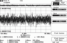
here a brief insight of Victor’s 1kHz oscillator(battery powered) - how it looks like on Modulation domain analyzer:
View attachment 1kHz Victor.bmp
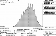
View attachment 1kHz Victor Histogram.bmp
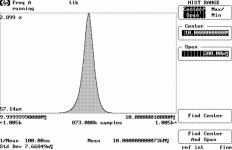
and how looks like a venerable 1MHz HP 10811 OCXO
View attachment HP 10801 10MHz Gaussian distribution.bmp
In all measurements the frequency span was the same - 200mHz
1kHz Victor.bmp
1kHz Victor Histogram.bmp
HP 10801 10MHz Gaussian distribution.bmp
Last edited:
Sorry didn't well manage the uploads.
In the first pictures we can see the frequency distribution over time - we see oscillators stability, but also where is the mean frequency.
In the beginning oscillator drift is pretty high-more than 20Hz, and then after 20min
drift is is not so big and oscillator is more or less stable.

Second pictures shows the same, but this time like histogram, where we see more precise what is going on.
Presented are more different frequency peaks within the mean frequency.
We must consider that we are looking into extremely narrow frequency band on the mean freqency( -100mHz - Mean - +100nHz )- the whole frequency width is only 200mHz.

Third picture presented what is possible and how looks one almost perfect oscillator. We can see how pure-very low phase noise, and how stable 1MHz oscillator is. Perfect Gaussian distribution - as in theory books!
It is the same frequency span.

In the first pictures we can see the frequency distribution over time - we see oscillators stability, but also where is the mean frequency.
In the beginning oscillator drift is pretty high-more than 20Hz, and then after 20min
drift is is not so big and oscillator is more or less stable.

Second pictures shows the same, but this time like histogram, where we see more precise what is going on.
Presented are more different frequency peaks within the mean frequency.
We must consider that we are looking into extremely narrow frequency band on the mean freqency( -100mHz - Mean - +100nHz )- the whole frequency width is only 200mHz.

Third picture presented what is possible and how looks one almost perfect oscillator. We can see how pure-very low phase noise, and how stable 1MHz oscillator is. Perfect Gaussian distribution - as in theory books!
It is the same frequency span.

OK, clear. I'm still trying hard to see if this has any significance for an audio oscillator. I would think that the frequency deviation is still much less than the bin width of the typical (FFT) analyzer, or the rejection bandwidth of an analog notch.
Jan
Jan
Sorry didn't well manage the uploads.
In the first pictures we can see the frequency distribution over time - we see oscillators stability, but also where is the mean frequency.
In the beginning oscillator drift is pretty high-more than 20Hz, and then after 20min
drift is is not so big and oscillator is more or less stable.
View attachment 773502
Second pictures shows the same, but this time like histogram, where we see more precise what is going on.
Presented are more different frequency peaks within the mean frequency.
We must consider that we are looking into extremely narrow frequency band on the mean freqency( -100mHz - Mean - +100nHz )- the whole frequency width is only 200mHz.
View attachment 773503
Third picture presented what is possible and how looks one almost perfect oscillator. We can see how pure-very low phase noise, and how stable 1MHz oscillator is. Perfect Gaussian distribution - as in theory books!
It is the same frequency span.
View attachment 773504
Thanks for explaining this. I think it maybe goes to one of the oscillator design tradeoffs that usually must be considered. This is in regard to oscillator noise, both amplitude and phase.
Here is an example. Consider the distortion created by the agc control element, here a JFET. It is one of the significant sources of distortion in a typical oscillator. It is basically caused by the nonlinearity of the JFET resistance as a function of the drain-source signal amplitude. This is the distortion that we usually minimize by feeding back half of the drain-source signal voltage to the gate.
We can minimize this distortion by operating the JFET at a smaller signal level. However, in any oscillator design, the agc control circuit must have enough control range (authority) to adequately control the amplitude of the oscillation over various circuit parameter variations. If we reduce the signal across the JFET to reduce distortion, we must increase the injection gain for the correction signal going into the oscillator loop to keep the authority the same. This increases the amount of noise being injected into the oscillator loop by the agc circuit. Herein lies the tradeoff.
While we usually focus on and measure the oscillator distortion, it is also important in many applications to measure and be aware of oscillator noise. A simple example of this is in a traditional analog distortion analyzer. Oscillator noise and similar noise generated in the analyzer state variable filter will result in a higher analyzer noise floor. This can be seen if you look at the analyzer residual on a spectrum analyzer. Ideally, there will be no fundamental in that residual, but in reality you will see a spectrum about the fundamental frequency that has some width. This is largely due to noise that is close to the fundamental frequency.
Cheers,
Bob
Thanks Bob, clear. If the oscillator has phase noise, that then also causes phase noise about the harmonics, right? Does that matter as long as the bin width is larger than the frequency deviations?
Jan
Jan
- Home
- Design & Build
- Equipment & Tools
- Low-distortion Audio-range Oscillator