In all topology that use OITPC, I found at low level the harmonic level is almost monotonic, but at high level depend on topology. I think, OITPC only reduce high order distortion at low level.
Bimo, how compensation can be level selective? No, you observation is wrong, nothing to do with OITPC.
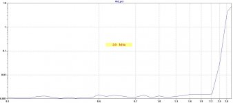
Attached the THD20k plot of the 200W CFA where OITPC was used, no much THD increase with input level.
Attachments
Last edited:
I have tried both, same problem
I am quite sure there is problem with oscillating cascode, look this link :More Notes On Cascode Amplifier Oscillation
You can tray to find what side of cascode oscillate by moving finger close to cascode transistor from the pcb back side and lookin on oscilloscope if frequency changes.
First try with 1nF XR7 ceramic caps between base and ground, and if still oscillate increase R11, R12 to 1k.
I built similar amp with one difference, instead resistors R5, R10 I used CCS and there was no oscillation. This one I wanted to simplify.🙁
Do you mean 1nf instead of 220pf from base of 5401,5501 to the gnd?
What is the matter, can we add flying ccs,?
What is the matter, can we add flying ccs,?
Last edited:
Do you mean 1nf instead of 220pf from base of 5401,5501 to the gnd?
What is the matter, can we add flying ccs,?
If you read linked document you can see it suggests XR7 ceramic dielectric, so better to replace 220pF with 1nF XR7.
try to connect R11 to +15V and R12 to -15V
Ok i will try.
Using the existing value, 330R?
Last edited:
Ok i will try.
Using the existing value, 330R?
Yes, and other side of resistor not one connected to the base, I say that just in case.🙂
Yes, and other side of resistor not one connected to the base, I say that just in case.🙂
Yes, this is clear🙂
Keeping or removing the addeted caps?
Keep the ones connected to the bases, for now, remove those from other side of the resistors.
This is keeping both
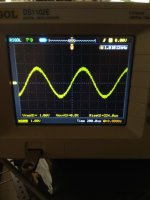
I didn't see the oscillation with no signal but i think still isn't good
I didn't see the oscillation with no signal but i think still isn't good
Attachments
Last edited:
This is keeping both
I didn't see the oscillation with no signal but i think still isn't good
This looks more like noise, could you look the MHz region?
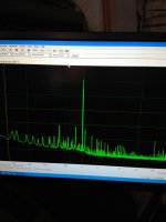
May be i must connect my generator, this was using ARTA and here is a screanshotThis looks more like noise, could you look the MHz region?
Attachments

Caps from the +/-15 v to gnd removed, same thing..
I think that you get this noise (if it's noise?) from +-15V. What zener resistor are you using, probably need to be of lower value to get more current to the zeners.
The used laterals are very sensitive to oscillation if the gate wire is very long - this may be the reason here. Try to cut the gate wire and solder the gate stopper resistor as close to the mosfet as possible.
BR, Toni
BR, Toni
The used laterals are very sensitive to oscillation if the gate wire is very long - this may be the reason here. Try to cut the gate wire and solder the gate stopper resistor as close to the mosfet as possible.
BR, Toni
Thanks Toni,
I don't think that are laterals, gate resistors are quite close to the gates, and oscillation of 20MHz is not coming from them.
BR Damir
Last edited:
+1
Then it is mostly to less GM/PM. Had a similar problem during my SA2016 development
Simulation models differ from the real devices.
Try to increase the miller cap until subtle oscillation stops.
BR, Toni
Thanks Toni,
I don't think that are laterals, gate resistors are quite close to the gates, and oscillation of 20MHz is not coming from them.
BR Damir
Then it is mostly to less GM/PM. Had a similar problem during my SA2016 development
Simulation models differ from the real devices.
Try to increase the miller cap until subtle oscillation stops.
BR, Toni
- Home
- Amplifiers
- Solid State
- Lateral CFA 120W - BSA