It looks very much like the example you sent me a few weeks ago.
It won't work very well in this condition, because the 33K FB resistor of your schematic is in fact the 2K2 FB of the latest EZmos version, and most other components should be scaled according to that resistor (not the 0.22ohm though).
The closed loop gain of the two amplifiers is different too, and that should also be taken into account.
However, the compensation needs to be tailored to the actual speaker, which means that you will need a lot of experimenting to find the right value(s) anyway.
As a starting point, you could use the same 0.22/4.7/15 triangle, to which you connect the 100ohm/220µ network of the EZmos, and the 2K2 FB.
You can then play with the 4.7 and 15 ohm to change the overall output impedance, and add a RC similar to the 6K8/100n to adjust the frequency response.
The end result will depend very much on your tastes and the speaker used.
Satisfactory values for one type of speaker will not be applicable to another one
I'd like the trouble constrained like this: The rather mild effectiveness isn't big enough to incur the cost of individual fine tuning....Satisfactory values for one type of speaker will not be applicable to another one...
The very mildly effective production example, 1978 through 1997, worked like "don't buy anything with a handle" in that there was no labor to use it.
That circuit didn't do much of anything except that reduced reliance on eq at amp input is also not putting gain to error. That alternative path is how the effectiveness is realized.
I apologize that I can't describe this accurately, but the point is resurrecting long forgotten amplifier features from days gone by, except with the new convenience of a much lower distortion amplifier today. The circuit posted is less likely to mismatch speakers than my tube amplifier. And, the students return to uni, studying fets in approximately four months.
Similar to 450R/1u5, Except that would be quite audible....As a starting point, you could use the same 0.22/4.7/15 triangle, to which you connect the 100ohm/220µ network of the EZmos, and the 2K2 FB.
You can then play with the 4.7 and 15 ohm to change the overall output impedance, and add a RC similar to the 6K8/100n to adjust the frequency response...
Oh, I see the problem.
I have made an error!
The target for 'matching' apparently wasn't a speaker. That got me confused.
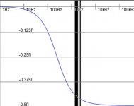
In the first attachment (that rc by itself), I've added the big black stripes at ear sensitivity peak frequencies.
In the second attachment, ISO226 is a good match for that shelf filter.
The production unit sounds like it matches any speaker because they had matched an ear instead.
Attachments
![400px-Lindos3.svg[1].png](/community/data/attachments/700/700168-8de57413f911fd709890859e8502c2dc.jpg?hash=jeV0E_kR_X)
Thank you for illustrating that!
partial current drive:
If it were an ordinary bass shelf, I'd think that an rc of 3k3/200n would be transparently mild. I'm not familiar with how much more the current drive part of the circuit needs. But, I think that I've overlooked something. Perhaps we should postpone the partial current drive.
auto center power:
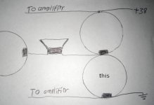
In the attachment is the simple method. The big cap marked "this" is the only part added to quick fit auto center power to a single rail amplifier. Practically, this one added part would do one of two possibilities: Either nothing noteworthy, Or a natural way to work more like a tube amplifier.
partial current drive:
If it were an ordinary bass shelf, I'd think that an rc of 3k3/200n would be transparently mild. I'm not familiar with how much more the current drive part of the circuit needs. But, I think that I've overlooked something. Perhaps we should postpone the partial current drive.
auto center power:
In the attachment is the simple method. The big cap marked "this" is the only part added to quick fit auto center power to a single rail amplifier. Practically, this one added part would do one of two possibilities: Either nothing noteworthy, Or a natural way to work more like a tube amplifier.
Attachments
Last edited:
I finally understood what "auto-center" was.
In fact, the output cap could be eliminated completely, because it is in series with the ones straddling the supplies.
The configuration will not naturally work with a normal, single supply amplifier, unless the supply is perfectly clean, because the output will see ~half the ripple present on the supply.
It is probably possible to arrange the FB network in a way that cancels this ripple (clean, regulated supplies are inconvenient).
I will think about it
Sort of looks like a cousin/attempt of bridging, without doubling load and parts count. That thread has the description sublimed JLH1969 except that the schematic doesn't make it clear that the speaker return is floated.
I had used the add one cap simple refit on my old zenith radio board and with an smps. What happened is that it played louder and clearer. I didn't find out the amplifier particulars with the tuner parts and glue on the board.
So, that has been a mystery. At other times when I tried to do it, what I achieved was adding another cap for no purpose whatsoever. There's probably another detail involved...
"auto-center" (sic) PSUs used to be the cheapest-of-the cheap way to work with a "dual-rail" (biplar supply) amp and a single-winding trafo. Usually a bridge, a resistor divider (faux-ground) and two reservoir caps. Often seen with the likes of TDA2030 or other cheap amplification etc.
I am afraid the inclusion of the "auto-center" feature is not going to be realistically possible: it requires the input and output GND's to sit at different AC potentials, which is not very healthy anyway, and to avoid injecting ripple into the speaker, some of that ripple needs to be injected into the (+) input of the amplifier.
This is problematic, because the source impedance will affect the compensating signal, meaning it will not be very accurate, and if the input is left open, the result will be disastrous.
This amplifier and the Old-Fashioned have been designed for a single-supply, and whilst conversion to a bipolar one would be possible, it needs to be complete, ie. both input and output referenced to the 0V, or the middle of the capacitive bridge if the GND is virtual.
A hybrid solution is not going to work very well, and will require extra complication, or a super-clean supply, none of which is desirable.
Item #1, ripple: At post#36, member anti suggested a 36v smps. This hits the center of the application range (better than I did). So, I have transmitted a 5a 36vdc smps to your location via a combination of, possibly sea turtles and horses. Well, the shipping was free and some of it might not involve petrol....avoid injecting ripple into the speaker...A hybrid solution is not going to work very well, and will require extra complication, or a super-clean supply, none of which is desirable.
Ripple? Damn the torpedos! Full speed ahead!
Item#2: As for the audiophile job to get done, it has costs. Right-on that it is necessary that costs for large signal shouldn't be done at small signal locale. Excellent! Also, I was thinking that some odd 220u shunt cap at small-signal/amplification locale after a resistor/transistor/diode series element?
With a 36V supply, and an amp that has good output swing, you can expect around 30W@4R, 20W@6R and 15W@8R rms output.
That's very kind of you Daniel, but really you should have asked before sending anything: I already have all the good quality test-supplies required for any situation, and in addition, I do not even need to make a physical test to know that it is going to work; in fact, even a sim is superfluous in this case.So, I have transmitted a 5a 36vdc smps to your location via a combination of, possibly sea turtles and horses. Well, the shipping was free and some of it might not involve petrol.
Ripple? Damn the torpedos! Full speed ahead!
It will work no matter, and the result will depend only on the supply's quality.
Thanks anyway, and it will be an opportunity to test the quality of a commonly available supply.
Most really good, performing solutions do not require a large investment money-wise, just good principles and practices.Item#2: As for the audiophile job to get done, it has costs. Right-on that it is necessary that costs for large signal shouldn't be done at small signal locale. Excellent! Also, I was thinking that some odd 220u shunt cap at small-signal/amplification locale after a resistor/transistor/diode series element?
Some do however, and one should be able to recognize when penny-pinching is not an option.
Could you provide a sketch of your shunt cap idea?
I am not quite able to visualize it
Oh, I had sent the supply because it is similar to what runs the working auto-center-power examples; and, also generally likely to be utilized. It was barely lunch-price and the real output is much better representation than virtualized media (photos, words). Caveat of a high efficiency production SMPS is that the filtering tends to catch some large signal audio too. . . or similar problem that I could not describe.
and,
Small signal power on the Honey Badger has the cap. In that case, resistor vs cap. I think it is there so that small signal doesn't get a rough ride when the big amp pushes a hundred watts to a speaker. Also, if a zener is added parallel to the cap, there's minimal parts count stabilized front end power. diyAB Amp The "Honey Badger" build thread R32, C11. Looks simple, except that I don't know best spot to install it.
Power ever increasing incrementally till infinity, or some form of overage management such as auto-center, baker clamps, etc? Well, ever increasing power is sure to result in impractical output; so, we need to have a closer look at overage management, carefully bearing in mind that the alternative has much worse costs.Can this circuit be upgraded to +50 Volts operation ?
Yes, if you need a higher output power and/or a higher load impedance.Can this circuit be upgraded to +50 Volts operation ?
If you use suitably rated capacitors and semi's, no problem at all.
With the latest version (with the additional input transistor), it is the only thing you need to keep an eye on.
I may have been misspoken (not intentionally). And a bit unfamiliar with fets. Had it been a BJT small scale (no drivers) amplifier that got a push-for-power request, I'd have a question about which low-cob toshi-specs driver or really stout CRT device to use for vas--some sort of have your cake and eat it too, performing device (which are few but do exist). But, as for fets, I've no idea.
@Elvee
Rather than laborious voltage increments, I did imagine one idea:
How far + is a missing reference point. So, what fet and outputs and voltage should be used for an up-sized not-so-EZmos? The device specs. Discontinued devices are OK for that example; but, what is important is the device specs necessary to achieve it. How far does it go before the performance droops or drivers needed; and, what does that line-in-the-sand example look like, if tamed for practical using? Well, I think that this is less laborious than sneaking up on it, incrementally.
It was supposed to be small/indoor scale; however, the high-low boundaries--nobody asked for the low side; but it seems necessary to document specs for the high side. Indeed, how does that go?
A possibly defined boundary may be at the output, since a highly competent diy edition of a husky/cheeseburger bookshelf speaker may resist cone breakup noises up to 68 Watts on measure. Those are rare, but it can be done. However, how much can the small scale style of FET amplifier do without performance droop or need of drivers? There's no need of that much indoors, in a house; however, there is need of a ceiling and what is it?
Of course 8W will do; but, when you've got a curiosity about how much (not past 68), then how much is it?
8 though 68, I think is a terrible question; but, I think that it is better than increments.
So much as 68 is neither requested nor desired; but, I'd like to know where the reasonable ceiling is? Perhaps the amplifier specs can reveal it?
I'd like to put in a request for less than 68W if small scale (small venue) purpose, indoors. Even half that much is overage for a fair speaker in a house. So, then the capacity, and the device specs to achieve it....
P.S.
To me, this looks like "the hard way" for overage management. I do not recommend the brinkmanship.
Last edited:
Diyaudio thought I could make sense in 30 minutes? Fail!
Anyway, if going without the costs of brinkmanship, then what does the + biggie size no-so-ezmos amplifier look like and what are the device specs to achieve it?
Anyway, if going without the costs of brinkmanship, then what does the + biggie size no-so-ezmos amplifier look like and what are the device specs to achieve it?
Dear LV & Daniel,
My thinking is that +50 Volts DC is convenient, the main capacitors can be 63 Volts rating. The output can be 16 V giving a nice ~30 watts output to 8 ohms. This level of output can be quite adequate for some.
SMPSs of 48 Volts rating are available.
If the voltage goes higher, we have to use higher voltage rated Elcos which are not easy to source everywhere.
--gannaji
- Home
- Amplifiers
- Solid State
- Easy-MOS is a simplistic, efficient and evolutive all-MOS amplifier for beginners