No, the forward drop depends on the bandgap of the particular semiconductor, which correlates strongly with the colour.~2V is standard forward drop for colored LEDs.
GaN LEDs are about 3--3.2V, this includes white, violet, blue and some green LEDs.
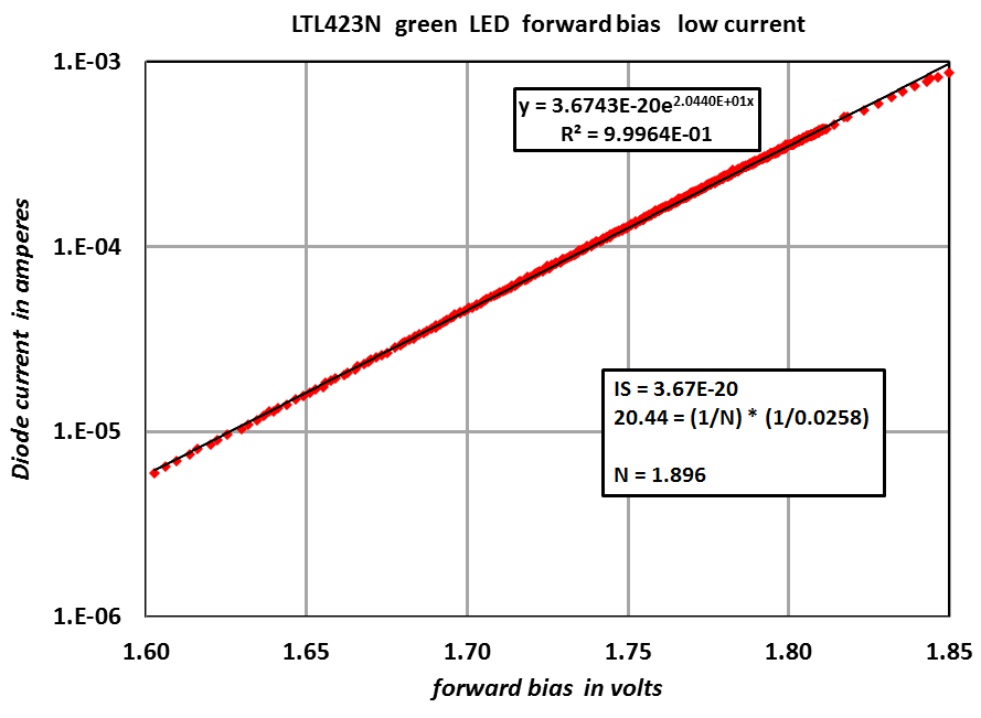
Common green LEDs are more like 2.5V,
yellow around 2.2V,
orange 2.0V
red 1.6V
infra-red 1.2V
But it does vary from these typical values depending on the structure of the LED and how hard its driven. These days LEDs use complex sets of layers to achieve quantum wells for efficiency (heterojunctions), so the effective bandgap is not necessarily natural for the colour produced, but needs to be enough to actually generate photons of that colour.
White LEDs are usually blue/UV LEDs (plus some phosphors).
I guess it's safer to use chain of well-defined 1N4148..
I'm assuming intended drop, according to the specs of the LED LV chose, will be 2V.
I'm assuming intended drop, according to the specs of the LED LV chose, will be 2V.
No, the forward drop depends on the bandgap of the particular semiconductor, which correlates strongly with the colour.
GaN LEDs are about 3--3.2V, this includes white, violet, blue and some green LEDs.
Common green LEDs are more like 2.5V,
yellow around 2.2V,
orange 2.0V
red 1.6V
infra-red 1.2V
But it does vary from these typical values depending on the structure of the LED and how hard its driven. These days LEDs use complex sets of layers to achieve quantum wells for efficiency (heterojunctions), so the effective bandgap is not necessarily natural for the colour produced, but needs to be enough to actually generate photons of that colour.
White LEDs are usually blue/UV LEDs (plus some phosphors).
Walt Jung simply standardized on one single (WIDELY available) LED part-number, and uses that one single LED type, with no substitutions permitted.
Design Document: https://www.diyaudio.com/forums/att...-reference-cell-_walts-blog-2014_092418_r-pdf
Design Document: https://www.diyaudio.com/forums/att...-reference-cell-_walts-blog-2014_092418_r-pdf
This may sound like nitpicking, but the N version is not a "quasi" amplifier, and neither is the Circlophone or the Circlomos.I know 🙂
For some strange (historical ?) reason, I'm only interested in Quasi amps..
Quasi is the short form for quasi-complementary, meaning any complementary amplifier can be changed into a quasi by substituting the P output device with a CFP composite, equivalent to a P device.
Conversely, any quasi amplifier can become a true complementary amplifier by changing the CFP for a NPN, or N-darlington.
This is not the case of the amplifiers we are discussing here: the OP's are homogeneous.
For the Circlophone, CFP's are used (but it has also been built in darlington and NMOS versions), but both the OP's are identical, and CFP.
In fact, those circuits bear more topological resemblance with full N historical versions, like the archetypal Circlotron, or the totem-pole, used in OTL amplifiers by Philips for TV amplifiers.
The advantage of such amplifiers, compared to quasi or complementary, is the perfect symmetry of the OP devices, leading to a deep cancellation of even order harmonics (I know: people go great lengths to achieve exactly the opposite, but I do not see an amplifier as a special effect box: there are numerous specialized gadgets doing that perfectly well, and they can be tuned, or simply bypassed when you are tired of them).
A true circlotron is a PITA, because of floating supplies and similar "details", but with transistors it is possible to "cheat" at the drive level to achieve the same perfect symmetry without the folklore and inconvenients of a true circlotron.
These are the circuits I generally present.
However, I have unearthed an interesting prototype in my huge "hardware archives", probably built 20 or 25 years ago, and apparently belonging to the "totem pole family", with a single phase-splitter.
I fired it up, and it woke up gracefully, delivering >50W on a 5 ohm load.
The THD is comprised between 0.05% and 0.5%, depending on the output power and the load.
Interestingly, it does not use emitter resistors, yet has stable quiescent current, and although it has no diff-amp input, it is DC-coupled and uses a symetrical supply (but it is apparently a natively single-supply amp modded to work in symetrical mode).
I haven't found the schematic yet: my paper archives, notebooks, folders etc form heap 2~3feet high, so it may take some time.
In fact, it might be simpler to reverse-engineer it, since it only count 6 transistors.
It fits your bill anyway, and it would probably be fun to see how it simulates (it was built and tested well before the sim era)
The LED is not critical, and any shade of red will do, as the voltage will be comprised between 1.5 and 2.2V, which is accurate enough.I guess it's safer to use chain of well-defined 1N4148..
I'm assuming intended drop, according to the specs of the LED LV chose, will be 2V.
Attachments
I guess it's safer to use chain of well-defined 1N4148.
But that will give much poorer regulation. LEDs are stiffer voltage sources than a string of many pn-junctions - basically you want one junction only if possible. Above 5V or so zeners start to become usable voltage sources, but the low voltage ones are the soggiest sources. Zeners need decoupling to reduce the noise.
LEDs are great little non-critical voltage sources because they come in a range of voltages, can double-up as status indicators, and are low noise (compared to zeners).
I have now uploaded a new toy for you to experiment:I know 🙂
As soon as I'm done with Circlophone build (very soon), this will be the next project. For some strange (historical ?) reason, I'm only interested in Quasi amps..
https://www.diyaudio.com/forums/sol...storic-amplifier-archosaurus.html#post5933988
Be warned: it is an authentic dinosaur 🙂
I guess it's safer to use chain of well-defined 1N4148..
I'm assuming intended drop, according to the specs of the LED LV chose, will be 2V.
Don't be misguided by the existence of exotic LEDs with significantly different forward voltage. Most LEDs are around 2V.
But there is a "better" option: Band gap shunt regulators.
The two common parts are TL431 and TLV431.
But beware that the slight difference "V" in part numbers means the reference voltage is 1.25V vs 2.5V, a big difference. Using a simple divider, the shunt voltage has to be higher than that reference so you can't get a 2V shunt using a 2.5V reference.
And be aware that because these use feedback for programming, they can be unstable, so a shunt capacitor is advised.
Another option also based on a 1.25V reference is LM317L where a series regulator can be used.
Last edited:
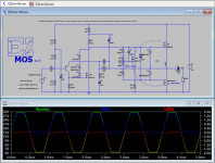
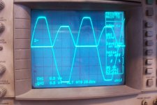
Clipping behavior
I was playing with some old downloads and I dug up this one and found that the clipping behavior was not great. When the gate is driven outside the linear range, there is a delay to return the gate back to a useful voltage. This creates rail sticking, and, shoot through currents when coming out of clipping.
I had assumed that people put Zeners on MOS gates to protect them from over voltage, but it seems it also reduces rail sticking and shoot through. If the power MOS vto are small wrt the on voltage, you might also want a series diode to block forward Zener current.
And there is also a similar issue with a MOS VAS, but you need a stack of diodes instead of a Schottky because the gate has to stay up at vto, which is about 2V.
Attachments
I think you _always_ want to block forward zener current, so either a series diode, back-to-back zeners (available in a single package in SMT!), or a bidirectional TVS diode.I was playing with some old downloads and I dug up this one and found that the clipping behavior was not great. When the gate is driven outside the linear range, there is a delay to return the gate back to a useful voltage. This creates rail sticking, and, shoot through currents when coming out of clipping.
I had assumed that people put Zeners on MOS gates to protect them from over voltage, but it seems it also reduces rail sticking and shoot through. If the power MOS vto are small wrt the on voltage, you might also want a series diode to block forward Zener current.
Whatever the forward drive voltage one MOSFET sees will be the negative drive on the other one, and any diode conduction due to this will modulate the VAS current and cause distortion. So make the protection components electrically invisible during normal operation.
It depends on the value of the MOS vto. If vto is 4V and clipping happens before each MOS gets to 8V then the zeners will never be forward biased. It's possible that plain 1n4148 on each gate could be used to limit the gate voltage to 2x the bias (vto) voltage, ie each diode protecting the opposite gate, but my simulations say that it should be about 6V and 8V would be too high, depends on the MOS. This is an old simple current limit circuit used on BJTs, not used much because the limit is not very well defined. That's another thing that limiting the gate voltage does, current limit.
You won't see shoot through current in the clipping voltage, and rail sticking is not usually visible at 1KHz.
You won't see shoot through current in the clipping voltage, and rail sticking is not usually visible at 1KHz.
Last edited:
- Home
- Amplifiers
- Solid State
- Easy-MOS is a simplistic, efficient and evolutive all-MOS amplifier for beginners