See photo below. You can use a DVM to test continuity between that and the input power connector.
But do we have to cut those too?
@big bird...
Yes. If you don't, they are still all connected at the input. You don't have to (or even want to) cut them entirely loose as @jacklee says, just use a sharp hobby knife to cut through the copper trace on each.
Greg in Mississippi
Yes. If you don't, they are still all connected at the input. You don't have to (or even want to) cut them entirely loose as @jacklee says, just use a sharp hobby knife to cut through the copper trace on each.
Greg in Mississippi
You listened to mistedogs' stack yourself? With the same amplifier and speakers? No difference between systems except which one the clocks are plugged into? If so, that's kind of strange, but potentially useful information. In that case the problem could be possibly due to differences in environmental RF at your place or mrdogs.
Regarding stereo separation, ESS advises to keep the two AVCC channels separate: http://www.esstech.com/files/4514/4095/4306/Application_Note_Component_Selection_and_PCB_Layout.pdf (it is well worth it to read every word in that document very carefully)
Also, I have two reference dacs here. One is Benchmark DAC-3, and the other one is an ES9038Q2M dac of my own design (which one professional high end audio designer said sounded better than the well-known and highly rated DAC-3). The stereo separation in both dacs is exactly the same, and far better that the dac we are working on in this thread. I followed ESS advice for my own AVCC power supplies. Works quite well that way.
I don't doubt your assertion re separate AVCC for left and right channels. I read and re-read the link you provided and found it to very interesting letting the users know what design decisions were made and why. However, I did not see anything that referenced or mentioned AVCC_L and AVCC_R. Or, at least I could interrupt as such. It may have been implied by one of the schematics that, more than likely I did not quite understand. Was that the correct link to the proper ESS application note? Perhaps you could point me to the figure # and comment in the app note where this is discussed.
Regarding the channel separation... you further state in a follow-up post that it is not 'very' severe. While this may have subjective interruptions, I would think for the re-creation of the accuracy of the music, any channel cross-talk would be a non-starter for any reasonably good piece of audio kit. The separation characteristic alone is a very significant element of how we ultimately hear the illusion of the original recording. Seems if that is not 'right', and can not be made right(Ian's design limitation), we're all wasting our time on other elements of the playback chain? 😉 However, since none of us were there during the original recording, how do we know what the production engineer ultimately mixed? Other than comparing it to another system and noting the audible differences.
This is bothersome to me, because once again, how do we ultimately know that what we're hearing is not being altered, shaped, or otherwise miss-interrupted from the source!?
I'm using a dual, mono-block amp design in my meager system and my sound stage and separation sound pretty darn good. Not to mention a whole host of other musical characteristics that I'm hearing for the first time in a very appreciable way. Since I don't listen too often with headphones, I can't make out the nuances of any channel separation or smearing differences, or my audible memory is just not that good anymore. What I can say is, there is plenty of separation using the Ian DAC-stack, and I'm pleased with the results I'm hearing.
I'm still tweaking my output-stage PSU and currently running the Jung-Didden super-regulator board. I can't say definitively if the sound is better or worse from what I had, just different, but in a good way. I'm still waiting for some film caps to try on the PSU input per your recommendation. They are on back-order until Sept. 🙁
Rick
I don't doubt your assertion re separate AVCC for left and right channels. I read and re-read the link you provided and found it to very interesting letting the users know what design decisions were made and why. However, I did not see anything that referenced or mentioned AVCC_L and AVCC_R.
They show an opamp AVCC supply for one channel, and emphasize the importance of using that particular supply schematic with recommended components and layout. The layout drawings show that there are two AVCC supplies. Same for the evaluation board schematic at ESS Technology :: Downloads ...I also have the evaluation board schematics for ES9038PRO, and ESS still uses separate regulators for each AVCC channel. AKM is doing exactly the same with AK4499 evaluation board. If you try it with separate supplies verses with a single supply, no matter how good the supply and filter caps, you will see for yourself why two AVCC supplies are always used for the best dacs.
Please let me say I got the Ian dac (running on power supplies, not batteries) sounding good enough that it could potentially get close to sounding as good as any Sabre dac ever can. The reduced channel separation is actually the limiting factor for what the dac can do. It is a deal-killer for me. What makes it tolerable is that the dac can still potentially sound pretty darn good in every other way so a little loss of stereo separation is probably easily tolerable to people who don't expect any better.
However, if you don't try the types of things I tried, you will never know how good the dac can sound. It will never get there only using clock upgrades, extra caps on clocks, discrete opamps, and the usual diy mods everyone seems to like to do.
On the other hand if you separate the boards as I did and wire it up to a JLsounds I2SoverUSB, convert your favorite CD rip to DSD256 or DSD512 using the demo version of HQplayer, and use good voltage regulation for the dac and output stage supplies (as I did) then the dac can sound so good it will totally blow you mind. Saber dacs don't get much better than that, maybe not any better (except for the lack of full stereo, and no harmonic distortion compensation, and insufficient output stage filtering). The only thing that can't be fixed is the stereo. If I had continued with the dac, I would have written up posts on the HD comp and output stage fixes.
Funny thing is, I have given nearly-all-you-need-to-do away for free (except for how to diy HD comp), but I doubt anyone will try the whole shebang.
Note: for anyone interested, looks like we might be starting to get into diy HD compensation over in the 'ES9038Q2M board' thread. One member wants to learn how to do it so its time to go into the details on that.
EDIT: parts used for separating the dac boards were purchased at: Prototyping : Adafruit Industries, Unique & fun DIY electronics and kits
To separate the output stage, I used something like Uxcell a13040500ux0203 1 Pin Male to Female Jumper Cable Wires 20cm Long (Pack of 40): Electronics Cable Connectors: Amazon.com: Industrial & Scientific ... and just taped the ends together then folded the wires over and taped them in position to reduce as much HF junk/garbage as possible (whatever cleans up the sound, probably twisted pairs for the dac +- outputs for each channel would be better than straight ribbon, but didn't take time to try it as I was working on the bigger problems first).
Last edited:
...On the other hand if you separate the boards as I did and wire it up to a JLsounds I2SoverUSB, convert your favorite CD rip to DSD256 or DSD512 using the demo version of HQplayer, and use good voltage regulation for the dac and output stage supplies (as I did) then the dac can sound so good it will totally blow you mind. Saber dacs don't get much better than that, maybe not any better (except for the lack of full stereo, and no harmonic distortion compensation, and insufficient output stage filtering). The only thing that can't be fixed is the stereo. If I had continued with the dac, I would have written up posts on the HD comp and output stage fixes....
I noted an image of your Ian setup in an earlier post (#445). I even printed it out for reference and it's in my build guide. When I get the final tweaking done on this DAC-stack, I plan on putting it in a proper case. At that time, I will likely separate the stack where it makes sense to minimize potential interference between the boards. Also bring the little display to the front panel. Maybe put the RPi in a metal case by itself.
As I mentioned, I'm also testing a couple different PSU approaches for the output stage as well, and will settled on what sounds the best to me in my setup. I do still want to try the film caps as well. In addition, I need to add the class D regulators for; DVCC, AVCC, and VCCA. I recall you mentioned I will need to feed those with a separate 6-9VDC supply? Can that supply be a well-regulated LDO-based PSU, or something different? I was planning on tapping off a 9v supply and regulate it first down to, say 6.5v? I have a couple of the low noise, DIYINHK boards with selectable voltage. Can all three be driven by the same supply as well? With enough current obviously.
Rick
At that time, I will likely separate the stack where it makes sense to minimize potential interference between the boards.
I would suggest doing it sooner rather than later so you can what effect it has on sound quality. No need to listen to extra distortion for longer than necessary. Also, it may affect your thinking about how you want to package the unit if you hear how good you can get it to sound now.
In addition, I need to add the class D regulators for; DVCC, AVCC, and VCCA. I recall you mentioned I will need to feed those with a separate 6-9VDC supply? Can that supply be a well-regulated LDO-based PSU, or something different? I was planning on tapping off a 9v supply and regulate it first down to, say 6.5v?
Actually, I described in one post you might have missed that once I increased the regulator input voltage to 6.7v and added a 33-ohm, 1/2-watt resistor from the output to ground for the AVCC regulator, that I found the TP Trident-SR and Trident-AVCC ADM7150-based regulators to sound better than NewClassD regulators (for 3.3v use only, haven't compared for +-15v yet). Also, I am not done trying to see how good I can get ADM7150 to sound for AVCC use (there is something new I have in mind to try), but any results with the dac I have switched to working on now will probably be reported in the ES9038Q2M board thread, rather than here.
Regarding your diyinhk regulators, it depends on what components are used on the boards. When you want to consider changing the voltage, we could talk about how to do it and what voltages are likely to be safe for the various components.
Last edited:
I would suggest doing it sooner rather than later so you can what effect it has on sound quality. No need to listen to extra distortion for longer than necessary. Also, it may affect your thinking about how you want to package the unit if you hear how good you can get it to sound now.
Actually, I described in one post you might have missed that once I increased the regulator input voltage to 6.7v and added a 33-ohm, 1/2-watt resistor from the output to ground for the AVCC regulator, that I found the TP Trident-SR and Trident-AVCC ADM7150-based regulators to sound better than NewClassD regulators (for 3.3v use only, haven't compared for +-15v yet). Also, I am not done trying to see how good I can get ADM7150 to sound for AVCC use (there is something new I have in mind to try), but any results with the dac I have switched to working on now will probably be reported in the ES9038Q2M board thread, rather than here.
Regarding your diyinhk regulators, it depends on what components are used on the boards. When you want to consider changing the voltage, we could talk about how to do it and what voltages are likely to be safe for the various components.
Mark - Check your PMs on this topic.
Transformers
A question for those who know about such things: I have a pair of Sowter 1:1 transformers that were previously used on the output of a DDDAC. Would they be suitable for use with Ian’s DAC?
A question for those who know about such things: I have a pair of Sowter 1:1 transformers that were previously used on the output of a DDDAC. Would they be suitable for use with Ian’s DAC?
Hi Greg and Anyone,
I have got one Boss dac and if I want to get Ian's boards to improve its sound, could I use a Fifopi or Isolatorpi? I would prefer to use Fifopi since it has reclocking function and I am thinking to use 22/24 clocks. If it is Fifopi, is it just to connect Boss dac board on top of Fifopi? Do I need ESS controller with the Fifopi?
I have got one Boss dac and if I want to get Ian's boards to improve its sound, could I use a Fifopi or Isolatorpi? I would prefer to use Fifopi since it has reclocking function and I am thinking to use 22/24 clocks. If it is Fifopi, is it just to connect Boss dac board on top of Fifopi? Do I need ESS controller with the Fifopi?
Last edited:
@Studley,
Those Sowter 1:1 transformers are likely 600R:600R ones. If so, they are functionally equivalent to the Onetics ones I use with my stacks AND that is my best transformer output setup so far. So likely a strong yes, I've heard good things about the Sowter line from others.
@latebloomer,
IF you have the original Boss, then putting it on top of the FiFoPi WITH upgrade clocks would be a good option. The minimum upgrade clocks I'd recommend are the NDK SDA from Lorien in the Group Buy forum here:
https://www.diyaudio.com/forums/gro...2520sda-oscillators-buy.html?highlight=lorien
These, BTW, are the same clocks Allo uses on the Boss 1.2. AND you also need to get a set of Ian's original clock adapters OR solder the clocks directly on the FiFoPi after removing the clock sockets.
Either way it is a fairly delicate and demanding soldering job.
AND you won't need an ESS controller with that.
In this configuration you need to change driver to a generic I2S driver for the stack to work.
Of course with the isolator stage in the FiFoPi, you HAVE to power the RPi and FiFoPi input separately from the FiFoPi output and the Boss. Best results would be if you used 3 supplies, 1 for the RPi and FiFoPi input, 1 for the FiFoPi output side, and 1 for the Boss.
IF you have a newer Boss 1.2, then my overall best results were not with a reclocker, but just an isolator... either Ian's or Allo's. My experience was that with the better clocks on the Boss 1.2 and Allo's improved power supply filtering, adding reclocking (such as with a FiFoPi or an Allo Kali) did not make the sound overall better to my ears... better in some way, but the 'magic' I heard from the Boss 1.2 was lost.
Of course for an original Boss, instead of a FiFoPi you could also use an Allo Isolator (or Ian's) AND an Allo Kali. BUT then your stack is higher and your power supply configuration can get a bit more complicated.
I hope this helps... and ask more quetions if needed!
Greg in Mississippi
@Greg,
Thank you very much. It is concise and well explained. I have listened to Ian to get IsolatorPi first to try it out. I also have one Odroid sbc so I think the IsolatorPi is versatile for both boards.
But that is something I don't understand, Allo site says Kali reclocker is not working for Boss which is master dac, so I also assume Fifopi won't help with Boss dac.
However, since you are able to make reclocker works with Boss dac, is that mean reclocker is a master and Boss dac is turned into slave mode? How do you make Boss working in slave mode? In addition, Is dac in master mode synonym with asynchronous mode?
@latebloomer,
You are welcome.
First, a question... which Boss version do you have?
Next, with either a FiFoPi or an Allo Kali, you operate the Boss (either version) in slave mode. Using a generic I2S driver makes this work (it may be labeled somethin. like that or as an ES9023 driver). I think the later Boss driver also had slave mode as an option you could select... check Allo's documentation or the driver in your setup.
Making a Boss work in slave mode only requires a driver that does not enable master mode and a master source. You can run a Boss directly on an RPi (no FiFoPi or Kali) in slave mode with a generic I2S driver quite easily. BUT I don't recommend it this way, both versions, when directly on an RPi, sound better in master mode.
Both versions of the Boss work in slave mode in addition to the typically used master mode. My experience with them is I preferred the original Boss in slave mode on a Kali (and an isolator, either Ian's or Allo's), but I preferred the Boss 1.2 in Master mode on an isolator (as above).
AND yes, when using a reclocker such as a FiFoPi or a Kali, it is the master for the DAC (Boss). BUT in the same way, in that situation the RPi is the master for the reclocker. The master is the unit who's clock is being used to generate the I2S data feed into the input of the downstream units.
RPi->Boss using a generic I2S driver, RPi is the master.
RPi->Boss using the Boss driver in master mode, Boss is the master BECAUSE its clocking signals are used to generate bitclock and LRclock signals that are sent back to the RPi which it uses to generate the Data I2S signal.
RPi->isolater->Boss using a generic I2S driver, RPi is the master for both the isolator and Boss.
RPi->FiFoPi->Boss using a generic I2S driver, RPi is the master for the FiFoPi, but the asynchronous reclocking in the FiFoPi makes it the master for the Boss.
Slave mode just means that a unit receives and uses the I2S datastream as sent and does not modify its sampling rate or synchronicity.
Asynchronous mode just means that the I2S signals after the unit performing the asynchronous reclocking are no longer synchronized with the master at the master unit. Since the FiFoPi receives the I2S stream into storage and sends it downstream reclocked to a local clock that has no connection to the original clock, it is an asynchronous reclocker.
The standard way of configuring ESS DAC chips is to have a fairly high frequency local clock (often 100Mhz instead of the common 45/49 Mhz clocks used in the FiFoPi or Kali) that is input into the DAC chip and an internal process reclocks the data to that clock... so the DAC chips themselves in the typical configuration are also asynchronous reclockers (ASRC).
I hope this makes sense (I don't make sense all the time!) and helps!
Greg in Mississippi
P.S. All of this is to reduce the jitter in the I2S datastream as received by the DAC chip which results in better sound quality. All are compromises with some pros and cons... that's why I prefer the original Boss in slave mode on a Kali and isolator (I haven't run one on a FiFoPi yet, but my initial comparisons suggest the FiFoPi with good clocks is at least the equal of a Kali), BUT prefer the later Boss in master mode without reclocking. It depended on where the best clocks were and how well the processing DID NOT add jitter (pretty much all processing adds jitter, the trick is to minimize how much is added).
Last edited:
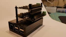
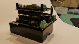
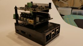
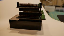
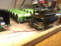
Wanted to post a proposed "DAC stack' customized for my planned enclosure. Using some 40-pin socket extenders (both 8.5 and 11mm), I was able to get the RPi, FifoPi and Dual DAC boards separated some, and the overall height to come in under my case height constraint of ~84mm.
As you can see from the pics, I took one of my plastic RPi cases that already had the opening for the GPIO connector that was very minimalistic to start as my base. Just to help with any stray RFI, I made a Faraday cage simply by lining the pi case with copper foil. I then added the first extender to raise the FifoPi roughly 15mm from the Pi (8mm from the plastic top). I then added another extender to raise the DAC board about 11mm above the Crystek clocks. Previously, they were so close to the DAC I had to use a small piece of electrical tape as an insulator so as to avoid any potential shorting with the bottom of the DAC.
I think this arrangement will work as it separates the boards and leaves enough room to the side of the DAC for regulator(s) I plan on adding. The I/V Std board will be connected with a piece of ribbon cable from the 10-pin header on the DAC. This way, everything will clear the top of my enclosure fine. The small ESS controller display will be moved to the front panel using the extender kit Ian offered in the GB. Anyone see any issues with this layout?
So far I'm very happy with the sound and it's made listening to older CDs (ripped to FLAC), and played using roon a real joy. Just about everything I've done to the DAC has made an improvement. Thanks to Markw4 for his added encouragement and guidance.
Rick
Attachments

Isolation shielding
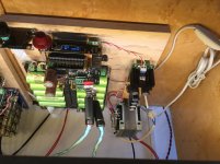
I have made a nice isolation shielding out of a bare pcb plate (one covered with copper surface and without holes, used to etch pcb’s)
The shield is placed above the fifopi and connected to ground (purple wire) of the fifopi (I do not know if it is the best place to ground).
I did not make comparisons yet, but it looks nice. An extra gpio pin header is used for more clearance (this must have a negative effect due to longer data paths)
I also made a simple linear power supply with a 100va transformer, some shottkey diodes and capacitors. The small ps in front is for powering the rpi.
Attachments

Last edited:
Nice isolation innovations
Two very cool approaches to isolation.
redjr sounds like you are enjoying some great sound.
Supersurfer, that looks like a 4 level DDDAC in the back ground. When you get Ian's stack all sorted, it would be interesting to get your impressions of the sounds of the two sources, particularly when they have similar clocks. I used the same PCB stock for isolation. Your implementation is quite neat.
Hi Wlowes,
If I remember well you were also present on the dddac thread some years ago. The dddac is modified by me to a great extent with a big improvement in sound, Doede has implemented some of my mods in his latest revision of the dac boards. It is interesting to have an ESS and Doede’s NOS dac next to each other; two completely different approaches.
I am not finished with tweaking the ESS dac but it is playing pretty well already, although the dddac is still the better one in detail retrieval, the ESS is very smooth in comparison (probably for a great part due to the AC and battery PS difference)
I just received the Andrea Mori crystals, so up to the next improvement!
Attachments
Supersurfer
I found the DDDAC project most interesting. While I never built one, I got a number of ideas that went into my dac project.
I will follow your clock upgrade with similar interest. I am waiting delivery of a 45/49 SC + oven. Initially I will replace the 45 NDK SDA with the 45 SC clock. In hindsight I probably should have just ordered a single 5mhz clock as I really only ever listen to redbook and the specs are compelling….future project. Should be a fun adventure.
The alternate test dac I started working on is getting pretty close to finished. It is sounding very, very good using HQplayer's highest quality upsampling to DSD512 settings. Really, it leaves any RPi dac in the dust for now, at least until there is a way to do RPi DSD512 (and with stereo AVCC). I keep trying to explain that power supplies, caps, and clocks can only do so much. Some people here are spending a lot on exotic parts for what in the end can only be mediocre sound quality, IMHO, given the limitations mentioned above. Pics can be seen here: https://www.diyaudio.com/forums/digital-line-level/314935-es9038q2m-board-454.html#post5817792
If anyone would be interested in building a dac more or less like that one, I would be happy to advise on mods and or settings that are found to help.
If anyone would be interested in building a dac more or less like that one, I would be happy to advise on mods and or settings that are found to help.
@Markw4,
Have you listened to one of Ian's GB setups in the full GB configuration powered by his LiFePO4 supply?
Greg in Mississippi
Have you listened to one of Ian's GB setups in the full GB configuration powered by his LiFePO4 supply?
Greg in Mississippi
Have you listened to one of Ian's GB setups in the full GB configuration powered by his LiFePO4 supply?
Seeing as how that is the first question I get, it looks like my words may have been taken as a critique of Ian and his products. That was not my intention. I don't know if there is any critique to be made at all. Rather there is perhaps a discovery and some recent developments in technology that will take some time for even small volume manufacturers to catch up with.
More specifically, I think with the new RPi board Allo is working on and with further streaming developments with HQplayer, Ian and cdsgames in another year or two will have dac products for you guys that will totally amaze you with how much better they are than today.
I am not a manufacturer at all. There is no lead time for what I do. It may take me a week or two to try out some new ideas and talk about the results online. I am enjoying sound quality right now that you will all have from Ian and cdsgames in another year or two.
What's the story? ESS dacs have always been capable of better SQ with DSD512 that with any other format. They don't advertise it, but some people have known it for quite awhile.
In addition, in the last few months HQplayer introduced the best upsampling to DSD algorithms in the world. Reportedly, the best sounding dac anyone can buy today is a T&A DAC8 DSD fed upsampled DSD from HQplayer. That's the word on the high end dac forums.
The first RPi dac products that have any chance of playing DSD512 may well be when Allo releases their new RPi type board. A dac will be needed to work with it, and Katana could be easily modified to do it. Although it takes a capable i7 processor to run HQplayer's best algorithms, before long it should be stream-able to an Allo high speed RPi.
All the above has little to do with Ian and what he can provide his customers right now. I'm sure the time will come, it can hardly fail to come given a little more time.
My only point is that I don't sell anything and thus can afford to develop prototypes very quickly for people at a level to be able to construct one. If anyone here wants the next developments in great dac sound quality right now without waiting a year or two, and if they can build from scratch, I am willing to help them do it.
Have said all that, I personally do scratch my head at some of the money a few people spend on certain parts. The problem with ESS Sabre dacs has much more to do with PCM vs DSD512 than many other things. That's not to say that power supplies and clocks don't have to be good. They do have to be good, but it can only help so much at some point when the biggest remaining problem becomes the PCM vs DSD12 gap. At that point, no amount of cables, clocks, and or power supplies can fix the biggest remaining issue. And please make no mistake, it that issue is a big leap, not a tiny difference.
Last edited:
- Home
- Source & Line
- PC Based
- IanCanada's Latest RPi GB Goodies Impressions... and your tweaks, mods and hints...