...one optimised for measurement and one optimised for 'sound'.
Actually, I would say the Katana output stage boards are mis-named. I prefer the sound of the lower distortion one, as do some other people. The other one Allo named 'sound quality' doesn't have better sound quality to everyone. It has filtering before the I/V stages that reduces one source of distortion and noise at the expense of increasing some other distortion even more. The boards differ in how they appeal to different people who listen differently. Which board seems preferable may also depend on how Katana is powered, and it is hard to say how many people are powering it well (especially vs how many people who may think they are).
D
Deleted member 537459
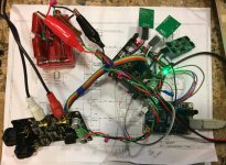
My setup now is neutron star clock, burson audio opamp v6 vivid and classic 3 different 3.3v for dac board and little polistirene caps(sandwich os 5 five 640 picofarad).

I applaud your hifi mess. I wonder if any of us will ever manage to make a good looking dac stack from all of this.
LOL... @sq225917... I don't listen with my eyes! If you check any pix of my gear I've posted, you'll see I practice what I preach.
BTW, did your connectivity fix result in any changes to the SQ? I am guessing not, but curious.
@ilgavro, love your setup! It looks like you used the relay-on signals from Ian's LiFePO4 board to control the relays on your 2-cell add-on board. Does that work ok or did you have to fiddle with it? AND how's it all sound to you?
Also, what's the copper stuff around the Burson's? Heatsinks?
@markw4, I'm curious why you don't re-configure Ian's IVStd to your DAC's IV circuit and values. The topologies are very close... you'd have to jumper the 100R in the IV stages feedback loop and the 33R in the output balanced to single-ended summing stage feedback loop. Then in addition to changing most of the values, you'd have to fit the 2.94k(?) between the 2.74R and 220pF on their side going into the summing stage - input. Then at least you'd have a similar circuit in the I/V, though not the same implementation.
Going through that also has me curious why you are focusing on increasing the level of filtering in the summing stage instead of the IV stages? You'd responded to me earlier that you thought that the IV stages were not the place to have most of the filtering, but your IV stage has MUCH more aggressive filtering in the feedback loop than Ian's stock IVStd... 1700pf/820R in yours, 270pF/810R (Ian has the 2 1.62K R's in parallel) in his. Since Ian's IVStd's IV stages woud only require jumpering 4 resistors and changing the value of the feedback C to 1700pF, that re-configuration seems to be the easy quick hit for you. Just curious on your thinking here.
BTW, I'm settling on 1200pF to 1500pF in that position for my tastes and ears, along with adding the Rasmussen pre-IV filtering, which we know we disagree on it's merits (Re: the 2 different Katana Opamp stage boards).
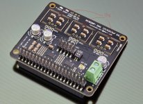
Also, i just caught your comment on the Katana DAC board where you said 'Most of the Katana dac PCB is taken up with power filters for each of the several Torex regulators.' By my count there are 7 LP5907 (labeled LLVB, LDOs 1-5, 8, 9), 2 that I'll have to get my microsope out to identify (too lazy, maybe these are Torex, LDO's 6 & 7), and 3 other IC's that aren't labeled as LDOs, but have packages that could be. Am I missing something?
Greg in Mississippi
P.S. @jimk04, any progress on your issue?
P.P.S. @Markw4, I just saw your post after this one. Good work. What are you using to power the JLSounds USB to I2S board?
BTW, did your connectivity fix result in any changes to the SQ? I am guessing not, but curious.
@ilgavro, love your setup! It looks like you used the relay-on signals from Ian's LiFePO4 board to control the relays on your 2-cell add-on board. Does that work ok or did you have to fiddle with it? AND how's it all sound to you?
Also, what's the copper stuff around the Burson's? Heatsinks?
@markw4, I'm curious why you don't re-configure Ian's IVStd to your DAC's IV circuit and values. The topologies are very close... you'd have to jumper the 100R in the IV stages feedback loop and the 33R in the output balanced to single-ended summing stage feedback loop. Then in addition to changing most of the values, you'd have to fit the 2.94k(?) between the 2.74R and 220pF on their side going into the summing stage - input. Then at least you'd have a similar circuit in the I/V, though not the same implementation.
Going through that also has me curious why you are focusing on increasing the level of filtering in the summing stage instead of the IV stages? You'd responded to me earlier that you thought that the IV stages were not the place to have most of the filtering, but your IV stage has MUCH more aggressive filtering in the feedback loop than Ian's stock IVStd... 1700pf/820R in yours, 270pF/810R (Ian has the 2 1.62K R's in parallel) in his. Since Ian's IVStd's IV stages woud only require jumpering 4 resistors and changing the value of the feedback C to 1700pF, that re-configuration seems to be the easy quick hit for you. Just curious on your thinking here.
BTW, I'm settling on 1200pF to 1500pF in that position for my tastes and ears, along with adding the Rasmussen pre-IV filtering, which we know we disagree on it's merits (Re: the 2 different Katana Opamp stage boards).
Also, i just caught your comment on the Katana DAC board where you said 'Most of the Katana dac PCB is taken up with power filters for each of the several Torex regulators.' By my count there are 7 LP5907 (labeled LLVB, LDOs 1-5, 8, 9), 2 that I'll have to get my microsope out to identify (too lazy, maybe these are Torex, LDO's 6 & 7), and 3 other IC's that aren't labeled as LDOs, but have packages that could be. Am I missing something?
Greg in Mississippi
P.S. @jimk04, any progress on your issue?
P.P.S. @Markw4, I just saw your post after this one. Good work. What are you using to power the JLSounds USB to I2S board?
Last edited:
Best sound out of this thing I have gotten so far. JLSounds I2SoverUSB v.III directly into dac board (MCLK from USB board NDK SDA). Film caps filtering +-15v from TP Placid-HD shut regulator for output stage. Feeding the dac native DSD256 via CD rip upsampled and converted to DSD by HQPlayer. Unfortunately, DSD256 is the highest this setup can go since MCLK from USB board limited by 22MHz and 24MHz onboard clocks. DSD512 from HQPlayer is reputed to sound even better.
Sound quality set up this way is far better than from RPi. Much less fuzzy distortion. Seems likely running RPi from linear supply would help, but the current setup demonstrates the probable limit of virtually perfect RPi isolation.
Still sounds like harmonic distortion compensation would help. Perhaps an opamp AVCC regulator would help too. Drums and guitar are not as percussive as they should be, and dark level between sounds is still not deep enough. On the good side, with HQplayer DSD the ringing that annoys Greg may largely be gone, sounds like it to me anyway. Also, its getting easier to tell individual singers apart when they sing harmonies due to what sounds like less intermodulation distortion.
Overall, at this point the dac still isn't up to the sound quality of DAC-3, or the sound quality of my 2nd modded ES9038Q2M dac, but its showing much more promise. Probably I will have to fabricate and test an opamp-based AVCC supply to try. Also will need to adjust HD compensation somehow, maybe give up using Ian's handy controller and use Arduino instead. Too bad because that will likely make it too complicated for most people to be able to experience the best sound the dac can likely produce.
Attachments
Last edited:
@markw4, I'm curious why you don't re-configure Ian's IVStd to your DAC's IV circuit and values.
I might do exactly that, eventually.
Might also put a cap across the dac outputs (but no series resistors). Regarding the I/V caps, I think they could be increased some, but doing all the filtering in one place only gives one pole which is far from ideal. Probably best to filter out the HF junk and leave the audio band essentially flat. For that it takes multiple poles. A Gaussian filter for a dac is a very good choice, since it preserves waveform shape (arguably important with percussive sounds). A multi-feedback Gaussian is really good because it has deep attenuation in the reject band. After good, clean SE outputs are working, those signals can be re-balanced if desired. Various ways to do that including with transformers.
As you can see from my last post (with the USB board), I am trying to examine a number of issues and prioritize mods based on experimental results. I could just randomly do everything I know how to do from the last dac, such as redo the output stage first, but that's not how I would like to proceed.
Note: The LLVB regulators on Katana are also the markings Torex XC6219Series uses. Probably just multi-sourced same parts, I'm guessing.
D
Deleted member 537459
@greg
around hai burson is of copper tape acts as a shield, the next step is to weld a ground wire to dissipate the noise. as for the second card, the food with the Ian card sounds great to me, it's direct without filters or anything. the end result is incredible, a friend of mine had a € 7k aurender and sold it to take this. the difference was remarkable.
around hai burson is of copper tape acts as a shield, the next step is to weld a ground wire to dissipate the noise. as for the second card, the food with the Ian card sounds great to me, it's direct without filters or anything. the end result is incredible, a friend of mine had a € 7k aurender and sold it to take this. the difference was remarkable.
I haven't actually turned it on with the new wifi/ethernet and ssd. My hifi room now has, Sara's, spendor bc1 and sp1/2 speakers in it, as well as my ns1000 and 63s. No space to move and that's not gounding the four CD players, tt stand and about 50kg of transformers and psu parts I've just inherited.
Might be a while before I listen to anything. Andvim building a Paradise phone for someone...
Too much stuff.
Might be a while before I listen to anything. Andvim building a Paradise phone for someone...
Too much stuff.
What are you using to power the JLSounds USB to I2S board?
A 5v Chinese LT3042 with pass transistor board. Replaced the big electrolytic filter cap with a nichicon 10,000uf, 35v, FW(M). Fed by a 9vac R-core transformer winding.
@Markw4 - Awesome troubleshooting tips. I removed the soldered wires to the PCB, installed pins for push on clips. I tested continuity from the top of the pin to the PCB trace, all is well. It still did not help. I ordered a new Dual Mono DAC Hat from Ian. I had ordered a Stereo DAC HAT. Put in on, reset all settings, put in the stock clocks. Worked. Then changed out the clocks to CCHD-957, changed settings as needed, worked. I'm leaving it as is.
When the new Dual Mono DAC Hat comes, I will solder pins to the PCB & CAP Cards. Then I'll just cut the 'IN' trace from the PCB & Cap card(s), put a jumper on there, test. Then I can pull that jumper, connect up separate 3.3v and hope for the best!
@Greg Stewart - Using the HiFiBerry MAX2PLAY web config image / tool, I can easily change out the driver, reboot and check it out. The image I'm using is a copy of the image that works great with the HiFiBerry DAC + Pro driver. I did test DAC +, did not try DAC + Light or the just plain DAC drivers.
Will try and report back.
When stuff does not work, it's easy to get discouraged, but y'all throwing out helpful ideas makes it fun again! Thanks for everyone's help.
Unfortunately, DSD256 is the highest this setup can go since MCLK from USB board limited by 22MHz and 24MHz onboard clocks. DSD512 from HQPlayer is reputed to sound even better.
The v.III comes with a 45/49 clock pair.
The v.III comes with a 45/49 clock pair.
Thank you, you are right of course. My bad. Will check again to see if I can get DSD512 working.
Last edited:
Well, no luck with DSD512 without doing some troubleshooting. It comes out distorted, maybe needs reclocking or something.
However, took another look at AVCC implementation on the dac board and Vref on the output stage board. Think I decided this dac's stereo is crippled in a way drastic surgery might be able to fix, but if I did it with the one I have probably very unlikely anyone else would do it too on theirs.
I have another dac board here I could be working on, a diyinkhk ES9028PRO board. I was hoping that Ian's dac would meet might needs while requiring less work on my part, but now I don't think so.
What I would say is that HQplayer can sound pretty good with a fast computer, even if stereo imaging is a bit compromised with this dac, the result of upsampling CD rips and converting them to DSD is far and away better sounding than straight PCM playback. No comparison really. For anyone wanting the best possible sound quality from this dac, I would strongly recommend trying it with high sample rate DSD. One way would be to use Ian's FIFO Pi and configure a JLSounds I2SoverUSB board to use external clocking from the FIFO Pi board. Skip the RPi itself.
It also helps SQ to separate the board stack as I showed in a few posted pics. Easy enough to try it and see. Almost half the battle right there. Between that and DSD most folks would end up with a much better dac than they ever expected. Probably better than playing around with the usual discrete opamps, exotic/expensive clocks, and polystyrene capacitors. Some of those things might help some, but they can't fix symptoms caused by other types of problems. Just sayin'
I put the DAC on one side of a copper ground plane and the FIFOPi on the other side from the get go. Just seemed like a fundamental design principal.It also helps SQ to separate the board stack as I showed in a few posted pics.
Good to hear that it is confirmed.
Seems to the easiest and cleanest solution to test/provide separate power rails for DAC with rollback option? Just to confirm, if understood correctly:I will solder pins to the PCB & CAP Cards. Then I'll just cut the 'IN' trace from the PCB & Cap card(s), put a jumper on there, test. Then I can pull that jumper, connect up separate 3.3v and hope for the best!
- Cut the connection only for IN trace between the DAC and daugther boards;
- Solder pins to all the GND and 3.3 holes on DAC side;
- For easy rollback can solder pins to IN holes on both sides;
- Connect separate power rails to soldered pins on GND and 3.3 holes on DAC side, while the daughter cards are still attached and GND/3.3 traces still connected.
Seems to the easiest and cleanest solution to test/provide separate power rails for DAC with rollback option? Just to confirm, if understood correctly:Did I get it right?
- Cut the connection only for IN trace between the DAC and daugther boards;
- Solder pins to all the GND and 3.3 holes on DAC side;
- For easy rollback can solder pins to IN holes on both sides;
- Connect separate power rails to soldered pins on GND and 3.3 holes on DAC side, while the daughter cards are still attached and GND/3.3 traces still connected.
For point #1 note that there are two bridges for power IN: one next to the IN mark and the other one at the opposite end, unmarked.
Rollback can also be done by simply connecting the three separate rails to the same battery rail.
I also found leaving the cap mini-board in place sounds better.
Well, no luck with DSD512 without doing some troubleshooting. It comes out distorted, maybe needs reclocking or something.
DSD512 would increase the DAC power consumption so check your DAC supplies, also someone else on here had similar issues and Ian posted a solution that involved terminating the i2s lines with 200ohm resistors ES9018K2M, ES9028Q2M, 9038Q2M DSD/I2S DAC HATs for Raspberry Pi
DSD512 would increase the DAC power consumption so check your DAC supplies, also someone else on here had similar issues and Ian posted a solution that involved terminating the i2s lines with 200ohm resistors.
Power supplies were fine in terms of current supply ratings. Main problem with higher sample rate DSD was probably due to the fact that wiring from USB board was not well suited to higher frequency RF. No doubt the scope would have showed the problem right away. Should be easy enough to fix.
Real issue that caused me to lose interest in further efforts with the dac was inability to power left/right AVCC separately. I already know how a Sabre dac should reproduce certain stereo tracks from listening to other good dacs. This one has a problem with the stereo separation that I attribute to the single AVCC power supply design decision. Stereo channel separation didn't sound like I expect a good Sabre dac to sound, so I decided to work with another dac instead, that's all.
Last edited:
For point #1 note that there are two bridges for power IN: one next to the IN mark and the other one at the opposite end, unmarked.
Rollback can also be done by simply connecting the three separate rails to the same battery rail.
I also found leaving the cap mini-board in place sounds better.
Hi jacklee , can you show me where is "bridge at the opposite end"?
Hi jacklee , can you show me where is "bridge at the opposite end"?
See photo below. You can use a DVM to test continuity between that and the input power connector.
Attachments
- Home
- Source & Line
- PC Based
- IanCanada's Latest RPi GB Goodies Impressions... and your tweaks, mods and hints...