... the IC near u.Fl ...It is marked 533 and I believe is an output buffer for mclk.
The part marked 533 is NB3L553: https://www.onsemi.com/pub/Collateral/NB3L553-D.PDF
It appears correct that the LT3042 only powers the clocks and NB3L553. The row of 6v electrolytics is input filtering for LT3042. If the caps were removed, then probably possible to power LT3042 from a bit higher input voltage. Might help its transient response. So might a resistor to ground at the regulator output.
I2S signals are clocked out of a SN74LVC374A D-Filp Flop, which is powered by a Torex XC6219Series regulator, and clocked by one of the NB3L553 outputs.
Last edited:
@Markw4,
Good info as always... and thanks for the chip IDs, I was too lazy this morning.
BUT I wouldn't try to power the LT3042 with a higher input V without further surgery. The LP5907 AND the Torex XC6219 LDOs that you identified share the same input voltage line. Specified max for the LP5907 is 5.5V, absolute max is 6V, the XC6219 is similar. Might be easier to do as @wlowes and remove the power pins to the clocks and feed them from another separate 3.3V source. That's one of the things I plan to do using both the ADM715x regulators AND that 2nd LiFePO4 board when I get to modifying the boards.
On your other comments...
Yah, even TP strongly suggested their Trident SRs were superior to their shunt versions. I had wondered how good the ADM715x regulators were when I started using them in 2016... TP's comments on the SR versions of their reg boards helped me feel good about them. BTW, do you have the AVCC set to 3.3V or up a little to the common 3.6V? OR can one even do that on the ES9038Q2M chip?
AND I forgot to mention thanks for noticing the AVCC/3 on the IVStd. That is different than how Ian did it on the other 2 prototype IV boards I have here... I'll ask him about that. BUT it is an easy thing to trial with the jumpering of one resistor.
One approach I'm taking regarding the Allo Katana versus the Ian GB gear is to focus on design and functional differences and how they might affect sonics. Regarding possible RF interference. both the Katana and Ian's DACs are sitting just one board away from the RPi. Although I haven't pulled a Katana and an Ian GB stack apart to confirm, I strongly suspect both the Allo Isolator 1.2 and Ian's FiFoPi have a full ground plane on the bottom. AND I have both an Allo Katana and Ian GB DAC board in front of me and can confirm they both have a full ground plane on the bottom. AND both have galvanic isolators in the data and other GPIO lines and separate power. SO why would the Katana not exhibit issues with RF, yet you suspect the Ian stack does? Of course, I also suspect you powered the RPi the same way in both cases, so that likely is not the culprit either, even though I don't like the sound of an Ian GB stack with the RPi powered by an iFi iPower. So far, a mystery to unravel.
Similar on the output stage filtering and clocks. Why does the Katana which uses NDK SDA's sound like it does, but a number of us are prefering the Ian GB stack with Crysteks? (Note, I DO KNOW with certainty that there are SDAs under the Katana metal shield... trust me on this one!). AND moving the Ian GB output stages filtering closer to that of the production Katana has worked well for me (with my ear-ringing issue, which I first discovered listening to the early Katana).
One significant difference between the Katana and Ian's GB gear is that the Katana has a bunch of power-rail filtering that was fine-tuned by Allo not only in the making of the Katana, but as they developed all of their products leading up to the Katana. AND that filtering does seem to maximize the performance of the Katana with less than stellar power sources while not damaging the performance with really good sources. It also allowed them to move to supposedly lower-spec'd regulator chips such as the LP5907 while still getting better performance than they got from LT3042's in their Piano 2.1, Kali, and original Boss DAC boards. On the other hand, Ian's GB gear is designed with power rail filtering optimized for use with alternative supplies such as his LiFePO4 supply. SO it does not surprise me that I get the best sonics out of the GB gear in my setup and to my ears with that or his developmental UCPi supplies. AND based on your work and that of @wlowes and @jacklee, among others, it seems to take a lot more effort and care with more conventional supplies to get good performance out of the GB gear.
2 things I suspect are notable advantages that the Katana has are the clock / DAC shields AND having the clocks less than 1" away from the DAC chip on the same circuit board. OTOH, I think powering Ian's GB gear with methods that synergize with its intent to work with alternative supplies, such as the local mid-sized (1F-1.5F) ultracap/supercaps with conventional AC-connected supplies that @wlowes pioneered, will maximize its performance both with those supplies and also Ian's intended alternative supplies.
@wlowes, I think your info of the impact of the BG at the clock buffer is vastly more important than my info. THANKS for that. When I get to that stage of refining, I'll remember that as a BG location. Luckily, I have a few of the .1uF and .47uF NXs left.
AND @Mikett, thanks for that reminder. The info on pre-loading regulators that I got back in the early 80s likely DID come from Walt Jung, though not directly from him. I don't remember seeing that mentioned in his articles, but I did have a lot of contact back then with some area engineers that connected with Walt and got a lot of info from him.
Later!
Greg in Mississippi
Last edited:
Interesting.. means in my case LT3204 only powers NB3L533 and 48mHz clock since I power 45mhz clock with its own supply. Now I am compelled to remove the 48mHz clock and see if there is a small improvement. I almost never use the 48mHz clock and could easily live without it.
Maybe nothing, but do not forget diyiggy and I are convinced that replacing the 3 ceramic caps took a little edge off the NDK SDAs. In my case I used a single .68u FCA that I had on hand plus another .47uF NX on top. With that the edge was gone and that may be key difference to the allo.Similar on the output stage filtering and clocks. Why does the Katana which uses NDK SDA's sound like it does, but a number of us are prefering the Ian GB stack with Crysteks? (Note, I DO KNOW with certainty that there are SDAs under the Katana metal shield... trust me on this one!). AND moving the Ian GB output stages filtering closer to that of the production Katana has worked well for me (with my ear-ringing issue, which I first discovered listening to the early Katana).
But now of course i also have a 1.5F SC also on the pins. The supercap drives delivers clarity, slam and dynamics. (and 3db of volume) I list what is there for full disclosure.
@wlowes,
Thanks for that reminder. I'll either solder up another adapter with NDKs or take the one I have already, remove the ceramics, and put in some film caps. I have 1uF, 10uF, and 22uF SMD films along with a bunch of smaller sizes. Looking at an adapter, I should be able to fit at least a 1uF along with a smaller film AND an NX.
AND what you're hearing with the local supercap/ultracap is similar to what I hear powering the FiFoPi and one of the GB DAC board each their own 325F UCPi float charged by an Uptone Audio LPS-1.2 each... though I suspect a local 1.5F on each will be another improvement.
Again, THANKS!
Greg in Mississippi
My pleasure Greg
My hunch wrt supercap is the bulk of the improvement came from simply having one 1.5F cap on the input power rail to the FIFO. So I suspect with UPCpi charged by Uptone you have everything and more than I have. But, I do not want to discourage you from direct supply to the clock as it will be interesting to validate if there is indeed more sonic juice to be squeezed.
My hunch wrt supercap is the bulk of the improvement came from simply having one 1.5F cap on the input power rail to the FIFO. So I suspect with UPCpi charged by Uptone you have everything and more than I have. But, I do not want to discourage you from direct supply to the clock as it will be interesting to validate if there is indeed more sonic juice to be squeezed.
a happy update
OK this was a happy coincident. Our discussion on cap's and Markw4 observation that the 555 IC shares the LT3204 with the clocks compelled me to remove the 48mHz clock.
Again the reason is to get pure clean power to critical success components. In my case I have isolated the ps to the 45mHz clock. With the 48mHz clock removed, the 555 buffer now also has its own supply. Recall it also has an extra cap on pins 1,4.
The result is taking the effect of the 555buffer cap to the finish line. There is another sonic blurr or jitter removed. It is felt across the audio range. I had been listening to really well recorded lessloss pieces featuring good recording with no audio engineering. Instruments are more clearly delineated. Also complex but compressed recordings that tend to get blurred now crystal clear. Melody Gardeau is a prime example. Lots of micro detail without the blurr.
I think this is a simple but significant change that will pay off regardless of downstream DAC. Might be even more significant in the highly resolved ESS DACs than on my vintage 1541a.
Thanks Jacklee. I completely removed the capacitor boards. Will double check the wiring.
LOCKL & LOCKR LEDs are lit up red.
In the manual: On Indicates... LOCKL - Left ES9038Q2M DAC U2 is locked to input music signals. Same for LOCKR.
LEDs are red
I've been looking for a photo of them lit up. They light up after I start a song, but no music.
Last edited:
LOCKL & LOCKR LEDs are lit up red.
In the manual: On Indicates... LOCKL - Left ES9038Q2M DAC U2 is locked to input music signals. Same for LOCKR.
LEDs are red
I've been looking for a photo of them lit up. They light up after I start a song, but no music.
Are you using the HiFi Berry dac driver, or what driver?
Also, do you have an oscilloscope?
What did you try so far?
LOCKL & LOCKR LEDs are lit up red.
In the manual: On Indicates... LOCKL - Left ES9038Q2M DAC U2 is locked to input music signals. Same for LOCKR.
LEDs are red
I've been looking for a photo of them lit up. They light up after I start a song, but no music.
I recall the led is green color when locked, not red. Are you using true-sync mode or async mode?
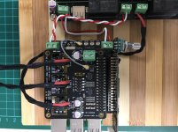
I attached a photo of my setup for your reference.
Attachments
TP's comments on the SR versions of their reg boards helped me feel good about them. BTW, do you have the AVCC set to 3.3V or up a little to the common 3.6V? OR can one even do that on the ES9038Q2M chip?
They are fixed voltage. Trident-SR are single 3.3v regulators. Tridend-AVCC are 3.6v with two separate regulators on one board.
Why does the Katana which uses NDK SDA's sound like it does, but a number of us are prefering the Ian GB stack with Crysteks?
Good question. Here is my question: Would we prefer Katana even more if they had designed it with Crystek clocks?
I assume the NDK SDA clocks sound as good as they do in Katana because of everything, the power they get with its filtering, the shielding, routing clock signals between board layers, etc. Most of the Katana dac PCB is taken up with power filters for each of the several Torex regulators.
We will probably learn more as time goes on and we do some more work on the Ian dac. Well, maybe. I am concerned right now about the absence of any way to separate left and right AVCC channels. The stereo separation is not like it is supposed to be, not nearly.
If you can get Ian to reveal where the AVCC traces run, maybe it can be hacked, cut, a wire tacked on, etc. Not sure if a fix is possible at this point.
One significant difference between the Katana and Ian's GB gear is that the Katana has a bunch of power-rail filtering that was fine-tuned by Allo not only in the making of the Katana, but as they developed all of their products leading up to the Katana. AND that filtering does seem to maximize the performance of the Katana with less than stellar power sources while not damaging the performance with really good sources.
Allo use pi filters everywhere, in and out of the Torex voltage regulators.
To change the subject a little, I will probably try a USB board next, maybe without FIFO_Pi. To understand the dac better and what makes it sound the way it does maybe helpful to reduce complexity. The JLSounds USB boards have clocks that can clock the dac and provide the I2S signals. It means only three boards are needed, USB to I2S, dac, and output stage. Once that much sounds the way it should (as much as possible), then clocking can be returned to FIFO_Pi, but without the RPi. See how that works, etc.
Funny you mention the stereo as being poor. For me that's one of the strong points of Ian's stack, much better than my Brooklyn was.
I've just fitted crystek clocks, not really hearing any great improvement from them. But at least the spluttering and wifi death that the ndk clocks induced has gone. I can only put that down to pin alignment on the ndk. As the same xo boards work flawlessly at misterdogs in his stack.
I've just fitted crystek clocks, not really hearing any great improvement from them. But at least the spluttering and wifi death that the ndk clocks induced has gone. I can only put that down to pin alignment on the ndk. As the same xo boards work flawlessly at misterdogs in his stack.
As the same xo boards work flawlessly at misterdogs in his stack.
You listened to mistedogs' stack yourself? With the same amplifier and speakers? No difference between systems except which one the clocks are plugged into? If so, that's kind of strange, but potentially useful information. In that case the problem could be possibly due to differences in environmental RF at your place or mrdogs.
Regarding stereo separation, ESS advises to keep the two AVCC channels separate: http://www.esstech.com/files/4514/4095/4306/Application_Note_Component_Selection_and_PCB_Layout.pdf (it is well worth it to read every word in that document very carefully)
Also, I have two reference dacs here. One is Benchmark DAC-3, and the other one is an ES9038Q2M dac of my own design (which one professional high end audio designer said sounded better than the well-known and highly rated DAC-3). The stereo separation in both dacs is exactly the same, and far better that the dac we are working on in this thread. I followed ESS advice for my own AVCC power supplies. Works quite well that way.
Last edited:
This may sound like a dumb question, but can you describe what you mean by stereo separation? It's tough to come up with a common vocabulary to describe this subjective sensation.
Reason I ask. I am getting a very large and well defined & precise sound stage from the FIFO. Using a different DAC and output stage of course. It depends on the recording but many recordings the stage is substantially wider than the speakers, and 2m back behind the speakers. The speakers are sonically invisible. Also a fair bit of 3d to it. There often can be 3 layers on the center where a Jazz singer is dead center but a bass is just behind her and a piano off to the right a bit but all in 3 distinct spots front to back. I never say it can't be improved, because when you think its perfect a tweak changes it all and you have to go listen to everything over again.
I have never heard a DAC-3. Wish someone in the area would bring something like that over to my room. 🙂
I am getting a very large and well defined & precise sound stage from the FIFO. Using a different DAC and output stage of course.
Channel separation isn't a FIFO issue. With Sabre dacs in general, it is strongly recommended by the manufacturer to use separate power supplies for AVCC_L and AVCC_R. Otherwise, stereo separation would be expected to audibly suffer, even with the best of power supplies. Using separate dac chips for left and right channels doesn't eliminate the effect. The main reason for combining both AVCC channels would be to simplify powering.
Dual chip has better crosstalk than single chip. There could be some modulation of the single avcc rail, but I'd still expect dual chip and shared avcc to do better numbers than single chip even with split avcc rail. You just can't beat the lack of on die modulation due to thermals. Of course dual chip and dual rail could be the tops.
Markw4
I don't doubt your assertion.
What I am trying to grasp is what is the audible impact of degraded channel separation. Just a curiosity. 😕
I don't doubt your assertion.
What I am trying to grasp is what is the audible impact of degraded channel separation. Just a curiosity. 😕
Markw4
I don't doubt your assertion.
What I am trying to grasp is what is the audible impact of degraded channel separation. Just a curiosity. 😕
Well, I assume you know the difference in sound between mono and stereo, right? This board sounds like it is about half-way between mono and stereo. Instruments that should be panned hard to the left or right and heard very distinctly in that one channel are instead blurred and somewhat more in the middle than they should be.
Well, I assume you know the difference in sound between mono and stereo, right? This board sounds like it is about half-way between mono and stereo. Instruments that should be panned hard to the left or right and heard very distinctly in that one channel are instead blurred and somewhat more in the middle than they should be.
What you described is very severe crosstalk which didn't occur in my setup. Perhaps it's due to some other factors?
A simple test would be to play some left-right channel identification track such as those Chesky test discs and then disconnect one side (e.g., left) and see if sound can be heard in the wrong side (e.g., left channel playing faintly in the right speaker).
- Home
- Source & Line
- PC Based
- IanCanada's Latest RPi GB Goodies Impressions... and your tweaks, mods and hints...