Yup no crosstalk here either. Playing a channel identification test track is exactly as I'd expect. Maybe one of your mods has allowed for this.
At es9038pro is for sure needed completelly separated supply for L and R. I measured signal amplitude modulation on supply pins. And carefully, no big caps for filtering, Because gnd is easilly poluted. Take scope put 1khz test signal and measure supply pins. On all of them will be easyiy vissible 1khz sinewave. I see it also on TCXO supply line. So regulators are already ready for each pin supplying, and modiffication in future must be done.
Similar at es9038q2m, there is also digital pin very noisy because of internal switching regulator.
Similar at es9038q2m, there is also digital pin very noisy because of internal switching regulator.
It appears correct that the LT3042 only powers the clocks and NB3L553.
I2S signals are clocked out of a SN74LVC374A D-Filp Flop, which is powered by a Torex XC6219Series regulator, and clocked by one of the NB3L553 outputs.
Correct me if I'm wrong, this implies that there are multiple regulators on the FiFoPi. So if I feed it with 3v3 from the LiFePO4 supply they will be in "pass through"
As established physically bypassing using the link positions on the bottom of the FiFoPi helps, but what is being bypassed here? All of the LDO's or just some of them?
I'm reluctant to get into cutting tracks and so the question that pops up for me is maybe it's better to feed FiFoPi with 5v and let the LDO's do their thing and get a bit more clock/processor isolation than have the rails commoned by pass through/ bypass?
Can you shed some more light on the FiFoPi topology please Ian?
What you described is very severe crosstalk which didn't occur in my setup.
No, it is less than very severe. There is some narrowing of the sound field and modulation of sounds in one channel by the other. It doesn't sound good to me, and it is exactly why ESS says to use two power supplies for AVCC, but that appears to be impossible the way this dac board is designed. That is what I am actually trying to describe.
Agree that powering the two channels separately will likely provide further benefits. I thought about this when doing the separate-rail mod and wondered if this is due to the use of batteries where it would not be easy to keep the voltage the same on both channels as battery voltage can vary a bit.
Nevertheless when compared to my other DACs I do not find the fifopi to exhibit a narrower sound field or any crosstalk so this may be system-dependent or some other factors might be contributing to it.
Let's keep experimenting to see how to take it further.
Nevertheless when compared to my other DACs I do not find the fifopi to exhibit a narrower sound field or any crosstalk so this may be system-dependent or some other factors might be contributing to it.
Let's keep experimenting to see how to take it further.
Speak to mister dog, he rates the stereo as its stand out feature. Though he does sit 5 feet from 989s...
Nevertheless when compared to my other DACs I do not find the fifopi to exhibit a narrower sound field or any crosstalk so this may be system-dependent or some other factors might be contributing to it.
Maybe your power amp or headphone amp has some cross-talk that masks the dac cross-talk? That wouldn't be unusual. Its the reason some people use mono-block power amps. In fact, TP sells an LME49600 mono-block headphone amp kit. Using the TP HPA showed me that there was some power supply coupled cross-talk in my regular HPA. I didn't know it until I heard what a stereo recording was actually supposed to sound like. The TP HPA kit is cheap for what you get, you might want to try it so you can hear the difference between cross-talk in different dacs.
Are you using the HiFi Berry dac driver, or what driver?
Also, do you have an oscilloscope?
What did you try so far?
HiFiBerry Driver. I actually have a HiFiBerry DAC. Ian’s Dual Mono DAC was working fine with a single power connection, but after I cut out the capacitor daughter boards and gave it the 3 way power treatment, no lock on R & L.
I checked the voltage on each, 3.3v. I put the generic clocks back in, reset all settings to default, still no sync / music. Installed Ian’s Stereo DAC Hat and its playing nicely. Upgraded the clocks, turned on synchronous clock mode, connected the MCLK signal from the FifoPi to J5 on the 9028Q2MPi using a u.fl coaxial cable.
I do have a scope. Not that swift in using it on digital signals.
@Simon Dart,
Because I like you so much, I spent some time probing one of the FiFoPi I have here to find the answers to your questions...
- Yes, the LDO bypass links DO bypass the 3 regulators we've already discussed on the FiFoPi... an LT3042, an LP5907, and an XC6219. These are all of the regulators I can find on the clean side. SO all of them are bypassed. This is why when you have the bypass links in, feeding the clean side with anything much over 3.3V will destroy the FiFoPi.
- The RPi side chips are fed from an AP7363 regulator. BTW, Ian appears to be using 2 of the Siliconex isolation devices, one on the top and one on the bottom of the board. AND the FIFO FPGA and memory are on the RPi side of the board, as one might expect.
SO if you want to provide better power isolation to the clocks, I suggest you do as @wlowes did (and @jacklee too, though by a very different method). Leave out the power pin on the adapters and feed power separately into each clock.
AND everyone, please play nicely. @Markw4, some of your comments are pushing the limits IMHO. Disparaging others' experience, equipment, or hearing is getting into Rule #1 territory. There were other's comments in the main FiFo thread also verging on Rule #1 territory. Play nicely!
@Mark24, remember that many of the others using Ian's GB gear are also using Ian's LiFePO4 supply to power their stack. AND when I compared, that bested my best AC-connected supplies. What they are hearing is likely different than what you are hearing. AND that goes for @wlowes too, with his AC-connected supplies AND local supercaps/ultracaps.
I DO understand that I did not test separating the rails on the DAC board (as you and @jacklee are doing), so I'm not hearing what you are at this point. That is why I have that on my planned set of trials AND will try that configuration both with AC-connected supplies (including ADM715x-based regulators similar to what you've been using) and a couple of LiFePO4 supplies, along with the local supercap/ultracap option for both.
Greg in Mississippi
P.S. @sq225917, I DO love your use of 989's as almost virtual headphones! That takes me back to the 1980's when I had a setup where I sat in the nearfield of a pair of Acoustat 2+2s!
Last edited:
I cut out the capacitor daughter boards and gave it the 3 way power treatment, no lock on R & L.
Some various troubleshooting thoughts, not necessarily in order:
IIUC, HiBerry is used for synchronous mode clocking. That means the dip switch and UFL cable status would have to be good.
Maybe close up in-focus picture of the 3-way power solder connections would be good to start with. I mean, if you were here that would be the first thing I would probably look at. Of they look good, then measuring voltages would come next, for all power rails.
You should be able to measure 3.3v power on the FIFO board clock pins, and the TI D-Flip Flop that clocks the I2S signals. Not sure what the third regulator on the FIFO board powers, but I would find one of those devices and measure the power on its pin to make sure its actually getting there okay.
The status LEDs appear to be mostly controlled by the Ian Sabre controller. It reads most if not all of the status from the dac registers.
One possible thing to look out for is that the little UFL cable connectors can easily get bent up from improper insertion/removal. In case the dac chips aren't receiving clocks, you might example the UFL connectors under a magnifier. Sometimes the ground prongs get loose from pulling the connectors out on an angle.
You should be able to see clock pulses on the UFL clock cable if you are very careful with probing. It is also possible to measure at the UFL connector on the dac board with a sharp tip probe where the socket center pin connection is soldered to the board. It may help to have two people, one to hold the probe and one to operate the scope controls (unless you are able to do one thing with each hand).
You can also use the scope to measure the 3.3v power you brought in verify good, stable, clean DC voltage.
If you can get it to the point you can hit play, then you should be able to see all three I2S signals on the 40-pin GPIO connectors using the scope. The clean and dirty connectors should both have the signals. Clean signals will have the FIFO delay added.
@Simon Dart,
Because I like you so much, I spent some time probing one of the FiFoPi I have here to find the answers to your questions...
- Yes, the LDO bypass links DO bypass the 3 regulators we've already discussed on the FiFoPi... an LT3042, an LP5907, and an XC6219. These are all of the regulators I can find on the clean side. SO all of them are bypassed.
SO if you want to provide better power isolation to the clocks, I suggest you do as @wlowes did (and @jacklee too, though by a very different method). Leave out the power pin on the adapters and feed power separately into each clock.
Greg, excuse me while I try out a little American:
You are the man

Thank you for that very useful piece of Sherlocking.... Of course I would have made the separate clock power option a lot easier to explore if I hadn't ditched the adaptors and soldered my clocks straight onto the board 😀
@simon dart...
A VERY forgetful man.
I DID think about this... if you think you can remove / replace the clocks without harm, you could:
1. Pull them.
2. Use solder-wick to clean the pads.
3. Solder a small tag of copper foil onto the power pad on the board with the tag end going past the end of the pad for access.
4. Put a small piece of Kapton tape over the power pad and the copper foil tag on the board, leaving the excess end un-covered.
5. Solder a small tag of copper foil to the power pad on the clock with the tag end going 90 degrees to the board tag.
6. Solder the clock back down onto the 3 pads.
7. Solder a small piece of wire between the tags to power the clock from the board.
8. Cover the board pad tag with Kapton tape and solder the wire lead to power the clock from an external supply.
Easy... except for the microscopic soldering!
@aguaazul, good troubleshooting tips from @Markw4. My question... Which HiFiBerry driver? AND did it ever work using that driver? The HiFiBerry DAC+Pro driver is designed for a DAC operating in master mode where the appropriate clock signal is sent to the RPi (as a bitclock signal) and the driver uses that as the master clocking signal to generate the I2S stream. That won't work with the FiFoPi and Ian's DAC boards which run in slave mode. BUT some other HiFiBerry DACs DO run in slave mode... their drivers will likely work with Ian's GB DACs. BUT you are safer using a generic I2S driver or one for an ES9023-based DAC.
BUT still, did it work with that driver before? IF it did, that isn't the issue.
Greg in Mississippi
P.S. The synchronous mode clocking that @markw4 mentions happens in the hardware configuration of the FiFoPi and Ian's DAC boards AND the settings in Ian's ESS DAC Controller. The driver does not participate in that, it has to be a slave mode driver.
So here's a tale of cautionary woe. Don't waste all your time wondering why your dac stack doesn't work and keeps dying with Volumio.
A. It's your wifi, it's crap, get a new router, extender, whatever.
B. Stop pulling the power plug numb nuts, there's a software power off in Volumio, start using that and stop corrupting your SD cards.
And that gentlemen is today's lesson. because my incredibly flaky dac stack worked perfectly round at Misterdogs last night.
Thumbs up for Moode from me also. I have not managed to corrupt even a single sd-card yet even after many stupid power-offs. And no wifi, no problems. 😀
@Greg,
Probably a good idea to forget about those 'optional' caps on the output stage schematic. Turns out they risk turning the differential summing circuit into an RF oscillator (perhaps depending on the particular opamp used and exact cap value). Too much phase shift around the inverting feedback loop. I should have paid more attention to the odd topology before trying it, anyway output stage is stock at the moment other than using OPA1612 for all three opamps and having the output stage board on ribbon extender rather than directly mounted to the dac board.
At the moment, an FFT is up and running running. I2S coming in via JLsounds I2SoverUSB v.III directly clocking dac board. FIFO out of the circuit for the moment. Will spend some time over the next few days looking at it in some more detail.
Last edited:
Markw4, You said you are an engineer, I assume data and measurements are very important to you, and you must have good equipments to measure them, can you post some measurements data of these RF interference, phase shift, Channel separation problem,etc you talk about, very keen to know, thanks
minivan,
On the one hand, I am a retired engineer. I don't have a lab full of equipment at home. There is a scope, a DVM, a sound card, a notch filter. That's mostly about it. No AP analyzer. In my working life, I did not specialize in audio equipment design either.
On the other hand, in the last year and a half I decided to work on trying to find a way to make good sounding audio dacs more accessible at low cost. What I found is that to get the kind of dac I would like to have and I think others would like to have, it takes trying to perfect almost every little tiny thing. Details of that journey are in the 'ES9038Q2M board' thread, over in the 'digital line level' sub-forum.
Also it turns out, IMHO, that the way we measure does not exactly correlate with the way we hear (and different people may hear very differently, a big subject I will set aside for now).
There are other complicating factors with dacs too, IMHO. People have started marketing dacs that measure quite well, but don't necessarily sound all that great for their price point. To my way of looking at it, if a dac doesn't measure pretty well there are probably related problems with it that are audible, but if dac does measure well that doesn't guarantee it sounds as good as another dac that measures about the same, or maybe as good as one that even measures a little worse.
The bottom line for me is that if I have some interesting measurements that could be useful to others, I would be happy to share them. If not, then not. Also, it shouldn't be too surprising if this project takes some time to sort out, or reach some kind of end point. All I can say is we will have to see how things develop over time.
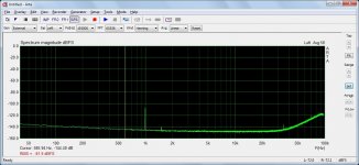
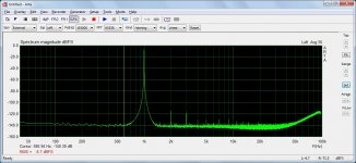
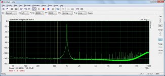
To follow up a bit on my last post, three screenshots of FFTs attached below. The first pic is 997Hz with dac volume level @-100dBFS. The 2nd one at 997Hz, 0dBFS clearly shows 2nd and 3rd harmonic distortion compensation would probably help reduce a little low level distortion. Changing the measurement frequency by 3Hz to 1000Hz as seen in the 3rd pic makes it look like 2nd and 3rd harmonic compensation might be fairly useless. In other words, the distortion changes with the frequency, and that's with only one frequency present. If there were lots of frequencies things would only get more complicated. Nonetheless, IME, performing adjustment of H2 and H3 in the dac registers can audibly help sound quality. So can improving output stage filtering at HF. One can't directly hear all the ultrasonic distortion spurs, but they may cause increased audible distortion in some power amps and some speakers. For whatever hard to pin down reasons, more filtering usually sounds better. I will think about redoing the design around the 3rd opamp on the output board.
Also, switching to DSD instead of PCM may improve the distortion situation vs frequency. That will be looked at later. The first thing is to get this part cleaned up as much as possible.
Also, switching to DSD instead of PCM may improve the distortion situation vs frequency. That will be looked at later. The first thing is to get this part cleaned up as much as possible.
Attachments
Last edited:
There are other complicating factors with dacs too, IMHO. People have started marketing dacs that measure quite well, but don't necessarily sound all that great for their price point. To my way of looking at it, if a dac doesn't measure pretty well there are probably related problems with it that are audible, but if dac does measure well that doesn't guarantee it sounds as good as another dac that measures about the same, or maybe as good as one that even measures a little worse.
You have summed that nicely, Allo found that with their Katana, and offer 2 output stages, one optimised for measurement and one optimised for 'sound'.
- Home
- Source & Line
- PC Based
- IanCanada's Latest RPi GB Goodies Impressions... and your tweaks, mods and hints...