I also recomend to read this paper. http://rmsacoustics.nl/papers/whitepaperMFBtheory.pdf
The high pass filter should be <= 16Hz and of order 6 or more.
Thanks, for the link!

rscamp have you calculated the efficiency when adding so much mass as shown in post #83 ? ;-)
No, but I'm expecting Fs to drop to 0.7Hz. 🙂
Been without DSL for almost a week due to a defective modem and look what I missed🙂 Kudos sofar Rob, impressive work !
Closing the dustcap should fix the 13hz, does the 270hz remain with feedback turned off ?
Does the 60hz remain with the StarBass disconnected @ eve ?
Closing the dustcap should fix the 13hz, does the 270hz remain with feedback turned off ?
😀rschamp have you calculated the efficiency when adding so much mass as shown in post #83 ? ;-)
Does the 60hz remain with the StarBass disconnected @ eve ?
Last edited:
High pass >= 16Hz and 6 order filter (or more)
This, or a notch filter, appears to be good advice. More to follow...
Been without DSL for almost a week due to a defective modem and look what I missed🙂 Kudos sofar Rob, impressive work!
Thanks, but In my own mind I feel like I'm still fumbling about. There is a lot to consider but it is certainly interesting!
Closing the dustcap should fix the 13hz, does the 270hz remain with feedback turned off ?
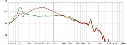
Well this is a surprise to me. The 13 Hz anomaly did not go away! The LF response did change as expected however (steeper rolloff) and the 270 Hz glitch almost dissappeared. See below - the lower trace was without the dustcap and damping material and the upper trace is with the dustcap and damping material.
The 13 Hz anomaly isn't coming from the EVE circuit. I bypassed it and the anomaly is still there.
Does the 60hz remain with the StarBass disconnected @ eve ?
No. And the 60 Hz diminishes with reduced feedback gain.
Attachments
This post is long winded because I'm thinking things though... 🙂
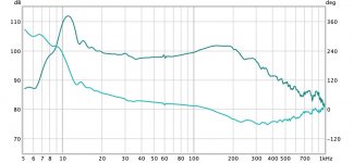
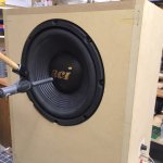
Here is the closed loop transfer function with what appears to be around 12 dB of feedback as measured with a microphone near field as pictured.
Some key observations:
- This is measuring ACOUSTIC output. We really should be measuring the ACCELEROMETER output to get better information with regard to any transfer function anomalies to better predict stability - particularly at higher frequencies where structural resonances will occur. Hopefully Chris will make this easier on future EVE board revisions. 🙂
- LF response is greatly extended to below 20 Hz (remember, the response without feedback and loop filtering normally rolls off at 12 dB/Oct below about 50 Hz with this closed box alignment!)
- There is a high Q resonance around 12 Hz - The frequency lowers with increasing Q as more acceleration feedback is applied. This is perfectly normal. I'm not sure if this is related to the 13 Hz anomaly in any way.
- There is an additional small anomaly from about 30-35 Hz. This also appears in open loop tests and the cause is unknown. I don't plan on worrying about it as it is so small.
- The 60 Hz noise can be seen
- The amplitude response rises near the upper limit of the feedback bandwidth (approx. 100-200 Hz). It turns out this is normal. As clarified by the reference kindly provided by esl 63 http://rmsacoustics.nl/papers/whitepaperMFBtheory.pdf , there is a bit of extra gain in this region above the upper limit of feedback bandwidth where feedback gain is falling below unity.
- Phase response is much improved with feedback exactly as expected. The phase shifts about 56 Deg. from 20-100 Hz. Without feedback correction, this would be about 180 Deg.!
So is MFB working?
No doubt. Outside of amplitude and phase response, performance hasn't been quantified yet to the bentoronto test specification though because significant changes to address more basic functionality are still being implemented. 😉
So what might improve performance?
Low Frequency Resonance:
This one is fairly obvious. It is clear that the low frequency resonance around 12 Hz with MFB needs to be tamed. To my knowledge, this resonant characteristic within the loop is unavoidable so this leads to the next alternative which is ensuring the control signal (preamp input) contains minimal energy at and near this frequency. This is where esl 63's recommendation for a near "brick wall" (6th order) high pass filter >= 16 Hz makes a lot of sense. The old "circa 1981" MFB system documented in another thread used a notch filter for this purpose.
Only a 2nd order high pass filter is built into the EVE board. This may be adequate depending on the cutoff frequency chosen and/or the nature of the audio sources. An example of where this would not be adequate would be where one wants the LF pole at 20 Hz and also wants to use a turntable as a primary source where the tonearm resonance is likely to be in this same region (perhaps 7-12 Hz).
So... For now I might compromise and get components for the EVE high pass filter to set the pole at 27 Hz. At least this will bring the input signal down about 12 dB at the LF resonance.
MFB Bandwidth:
It would be nice to move the "hump" in frequency response around 100-200 Hz upward to increase the feedback bandwidth. The near elimination of the issue at 270 Hz with the addition of the dustcap and damping material seems to make this even more possible. At the risk of beating a dead horse, this determination really should be made based on the accelerometer response. But in the interest of making this work with the equipment at hand and avoiding extra work (because it would be finicky with the current EVE board revision and I'm a bit lazy) I'll assume it is possible to widen the bandwidth based on the acoustic data.
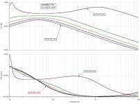
The table in Post #21 makes some observations on the effects of changing some of the EVE circuit component values. The candidates for change are C6 (Sensor low pass filter), and R17 / C10 (Loop Mixer). As it turns out, analysis suggests changing the caps would provide the most useful change and both are thru-hole (easy to change).
Reducing the value of C6 looks promising. This increases the "Sensor cut-off frequency" in the EVE manual and appears to do exactly what we want. The transfer function for changing C10 is also shown below but it is a bit misleading. It also appears to affect overall gain so its impact is less clear. If it is changed, the last image showing the open loop response indicates it would make sense to reduce the value to increase bandwidth.
C6 is currently 68n and I have 47n and 33n available for optimization/tuning. I'll be conservative and change C6 to 47n. Theoretically, this changes the "Sensor cut-off frequency" from 234 Hz to 338 Hz.
C10 is currently 100n and I have 68n, 47n and 33n available for tuning. I won't change this yet.
Board changes for the next iteration:
Low Frequency Resonance:
I didn't get components for the high pass filter so no change this time around.
MFB Bandwidth:
I try changing C6. I haven't checked that the second EVE board works okay yet so I might check that first to use as a baseline and then change C6 on the first board.
Here is the closed loop transfer function with what appears to be around 12 dB of feedback as measured with a microphone near field as pictured.
Some key observations:
- This is measuring ACOUSTIC output. We really should be measuring the ACCELEROMETER output to get better information with regard to any transfer function anomalies to better predict stability - particularly at higher frequencies where structural resonances will occur. Hopefully Chris will make this easier on future EVE board revisions. 🙂
- LF response is greatly extended to below 20 Hz (remember, the response without feedback and loop filtering normally rolls off at 12 dB/Oct below about 50 Hz with this closed box alignment!)
- There is a high Q resonance around 12 Hz - The frequency lowers with increasing Q as more acceleration feedback is applied. This is perfectly normal. I'm not sure if this is related to the 13 Hz anomaly in any way.
- There is an additional small anomaly from about 30-35 Hz. This also appears in open loop tests and the cause is unknown. I don't plan on worrying about it as it is so small.
- The 60 Hz noise can be seen
- The amplitude response rises near the upper limit of the feedback bandwidth (approx. 100-200 Hz). It turns out this is normal. As clarified by the reference kindly provided by esl 63 http://rmsacoustics.nl/papers/whitepaperMFBtheory.pdf , there is a bit of extra gain in this region above the upper limit of feedback bandwidth where feedback gain is falling below unity.
- Phase response is much improved with feedback exactly as expected. The phase shifts about 56 Deg. from 20-100 Hz. Without feedback correction, this would be about 180 Deg.!
So is MFB working?
No doubt. Outside of amplitude and phase response, performance hasn't been quantified yet to the bentoronto test specification though because significant changes to address more basic functionality are still being implemented. 😉
So what might improve performance?
Low Frequency Resonance:
This one is fairly obvious. It is clear that the low frequency resonance around 12 Hz with MFB needs to be tamed. To my knowledge, this resonant characteristic within the loop is unavoidable so this leads to the next alternative which is ensuring the control signal (preamp input) contains minimal energy at and near this frequency. This is where esl 63's recommendation for a near "brick wall" (6th order) high pass filter >= 16 Hz makes a lot of sense. The old "circa 1981" MFB system documented in another thread used a notch filter for this purpose.
Only a 2nd order high pass filter is built into the EVE board. This may be adequate depending on the cutoff frequency chosen and/or the nature of the audio sources. An example of where this would not be adequate would be where one wants the LF pole at 20 Hz and also wants to use a turntable as a primary source where the tonearm resonance is likely to be in this same region (perhaps 7-12 Hz).
So... For now I might compromise and get components for the EVE high pass filter to set the pole at 27 Hz. At least this will bring the input signal down about 12 dB at the LF resonance.
MFB Bandwidth:
It would be nice to move the "hump" in frequency response around 100-200 Hz upward to increase the feedback bandwidth. The near elimination of the issue at 270 Hz with the addition of the dustcap and damping material seems to make this even more possible. At the risk of beating a dead horse, this determination really should be made based on the accelerometer response. But in the interest of making this work with the equipment at hand and avoiding extra work (because it would be finicky with the current EVE board revision and I'm a bit lazy) I'll assume it is possible to widen the bandwidth based on the acoustic data.
The table in Post #21 makes some observations on the effects of changing some of the EVE circuit component values. The candidates for change are C6 (Sensor low pass filter), and R17 / C10 (Loop Mixer). As it turns out, analysis suggests changing the caps would provide the most useful change and both are thru-hole (easy to change).
Reducing the value of C6 looks promising. This increases the "Sensor cut-off frequency" in the EVE manual and appears to do exactly what we want. The transfer function for changing C10 is also shown below but it is a bit misleading. It also appears to affect overall gain so its impact is less clear. If it is changed, the last image showing the open loop response indicates it would make sense to reduce the value to increase bandwidth.
C6 is currently 68n and I have 47n and 33n available for optimization/tuning. I'll be conservative and change C6 to 47n. Theoretically, this changes the "Sensor cut-off frequency" from 234 Hz to 338 Hz.
C10 is currently 100n and I have 68n, 47n and 33n available for tuning. I won't change this yet.
Board changes for the next iteration:
Low Frequency Resonance:
I didn't get components for the high pass filter so no change this time around.
MFB Bandwidth:
I try changing C6. I haven't checked that the second EVE board works okay yet so I might check that first to use as a baseline and then change C6 on the first board.
Attachments

Last edited:
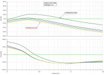
Changing C6 was worthwhile.
The diagram below shows the same amplitude trace with three values of C6 - 68n, 47n and 33n. 33n provides about 2 dB lower response in the region between about 100 - 200 Hz. Where the frequency response was 20 - 230 Hz +/- 3dB with 68n, it is 20 - 230 Hz +/- 2dB with 33n. Outside this frequency range there is little effect on the frequency response so a further change to C6 may be possible before the first instability occurs at a frequency other than 11 Hz.
In the previous post I dismissed any possibility of reducing the resonance at 11 Hz. But is there something that can be done? Chris - Could lowering the pole for the "Sensor highpass filter" below 2 Hz have any effect?
Attachments

With one or two caveats, I would guess this project is at or at least close to the point now where most people trying out the EVE board + Starbass accelerometer from Piratelogic would say they are done with optimization. Next is to confirm how well it works or maybe go right to working on other details of putting a usable system together like packaging the electronics. In my case, I haven't even tried it with the amplifier I intend to use so I'll have to confirm that works as well.
With regard to further optimization, I tried decreasing C10 below 100nF and the increased loop gain at lower frequencies seemed to make things worse rather than better. I also tried 150nF and this offered no worthwhile improvement so I ended up staying with a value of 100nF for this cap.
I found a 22nF with the correct package size at a local electronics store and tried that in lieu of 33nF for C6. This provided another small improvement in the flatness of the frequency response near the upper end of the feedback bandwidth. Now the frequency response as measured by REW and a UMIK-1 microphone is 20 - 230 Hz +/- 1.5 dB. It would appear further changes to C6 would provide little useful benefit.
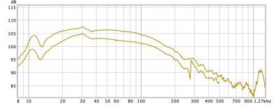
The image below shows the frequency response with and without feedback. The feedback factor reaches a maximum of 15 dB at 47 Hz and is at least 5 dB from about 20Hz to 110Hz. The feedback bandwidth extends from about 16 Hz to 180 Hz.
From this data we might say this system provides substantial correction of 2nd harmonic distortion up to about 55 Hz and substantial correction of 3rd harmonic distortion up to about 37 Hz. This system would completely cease to correct 2nd harmonic distortion at about 90 Hz and 3rd harmonic distortion at about 60 Hz.
I wanted a minimum of 15 dB of feedback and was hoping for more. The feedback gain can only be increased a little bit more with this setup before it gets really unruly at 11 Hz.
I could try to come up with a better optimization regimen that involves dissecting the EVE circuit board to directly observe the accel signal. My guess is I'm reaching the point of diminishing returns even with this step. One other opportunity still worth pursuing might be lowering the pole of the "Sensor highpass filter" mentioned in the previous post.
It still needs a "Rumble" (high pass) filter but other than that it could move on to validation testing where performance and usability are confirmed.
With regard to further optimization, I tried decreasing C10 below 100nF and the increased loop gain at lower frequencies seemed to make things worse rather than better. I also tried 150nF and this offered no worthwhile improvement so I ended up staying with a value of 100nF for this cap.
I found a 22nF with the correct package size at a local electronics store and tried that in lieu of 33nF for C6. This provided another small improvement in the flatness of the frequency response near the upper end of the feedback bandwidth. Now the frequency response as measured by REW and a UMIK-1 microphone is 20 - 230 Hz +/- 1.5 dB. It would appear further changes to C6 would provide little useful benefit.
The image below shows the frequency response with and without feedback. The feedback factor reaches a maximum of 15 dB at 47 Hz and is at least 5 dB from about 20Hz to 110Hz. The feedback bandwidth extends from about 16 Hz to 180 Hz.
From this data we might say this system provides substantial correction of 2nd harmonic distortion up to about 55 Hz and substantial correction of 3rd harmonic distortion up to about 37 Hz. This system would completely cease to correct 2nd harmonic distortion at about 90 Hz and 3rd harmonic distortion at about 60 Hz.
I wanted a minimum of 15 dB of feedback and was hoping for more. The feedback gain can only be increased a little bit more with this setup before it gets really unruly at 11 Hz.
I could try to come up with a better optimization regimen that involves dissecting the EVE circuit board to directly observe the accel signal. My guess is I'm reaching the point of diminishing returns even with this step. One other opportunity still worth pursuing might be lowering the pole of the "Sensor highpass filter" mentioned in the previous post.
It still needs a "Rumble" (high pass) filter but other than that it could move on to validation testing where performance and usability are confirmed.
Attachments
Last edited:
MFB working its magic...
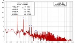
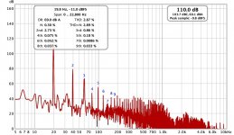
With the system unchanged from the previous post, here is the harmonic distortion of a 20 Hz signal as measured near field with REW and a UMIK-1 calibrated microphone at the same measured SPL - first without then with feedback.
Note that the excursion was not anywhere near XMAX in this test. I would estimate total travel was less than 10mm which is significantly less than 1/2 of XMAX. At higher displacement/SPL, the distortion without feedback would be considerably higher.
Attachments
Last edited:
Fabulous great results. Posts #93 and #94 would convince any MFB skeptic. Good if rscamp could post the audio recordings so we can hear for ourselves maybe on fancy headphones (possibly even YouTube would make sense, not sure). Of course, there's a certain philosophic issue of hearing something once removed.
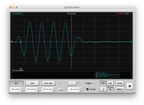
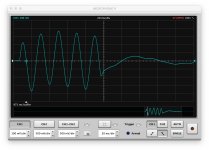
Here's my (largely just intuitive) take on the tone burst results, as eyeballed side by side. The MFB burst starts with a visibly (and probably audibly) bigger kick. That is what "fast bass" means.
The tail-end is strange. I think what looks odd about the tone termination is really some very low freq movements which look terrible but which are inaudible. Possibly with a HPF in place, it would look different. Likewise, that sharp peak on the last wave may be exaggerated due to MFB insufficiently reduced in the upper, less stable frequencies over 200 Hz. On music, the sub may never be triggered in that region, but the tone burst does trigger it. I think it is hopeless to try to make MFB work over 200 Hz and better to cut it up there inside the MFB loop, if possible.
I don't know why the MFB tone burst envelope has that odd wobble across the middle which may be a DC offset effect. I don't think it is audible or troublesome to the amp. But I wonder why it is there?
With MFB muscling the driver around, tone burst results can look very different according to the freq chosen. At some freqs, the MFB system may be less stable and the results look worse. At other freqs (such as around the speaker resonance), the comparison might be profoundly striking.
Not exactly clear to me why a sub (or any driver) should play nice tone bursts. The burst starts with a super fast acceleration and ends with a super fast abrupt stop. Linkwitz created mild tone bursts but that only changed the question to what should a mild burst look like.
B.
Last edited:
The tail-end is strange. I think what looks odd about the tone termination is really some very low freq movements which look terrible but which are inaudible. Possibly with a HPF in place, it would look different.
I don't know why the MFB tone burst envelope has that odd wobble across the middle which may be a DC offset effect. I don't think it is audible or troublesome to the amp. But I wonder why it is there?
bentoronto - I knew you would be waiting for test results like these! 🙂
The tone burst excites the 11 Hz resonance a bit. This shouldn't be a surprise given the transfer function charts in the preceding posts. The excitation is superimposed on the 50 Hz. To paraphrase your thought, extremely low frequency ugliness in the trace is inaudible and an excellent trade-off for the improved audible response.
With MFB muscling the driver around, tone burst results can look very different according to the freq chosen. At some freqs, the MFB system may be less stable and the results look worse. At other freqs (such as around the speaker resonance), the comparison might be profoundly striking.
Absolutely. And nothing I have presented this this thread is pre-selected as the best results or sugar-coated. No smoothing or bandwidth limitations have been applied. The tone burst response with feedback could quite easily look better at another frequency (probably a lower one where there is more correction of the harmonics for example).
Not exactly clear to me why a sub (or any driver) should play nice tone bursts. The burst starts with a super fast acceleration and ends with a super fast abrupt stop. Linkwitz created mild tone bursts but that only changed the question to what should a mild burst look like.
B.
It is all relative I suppose. Practically speaking, for a very low frequency driver to have good transient response it can have a much slower rise time than a higher frequency driver. If by some miracle of physics the operational feedback range of an MFB subwoofer being used to reproduce 20 - 120 Hz was extended to 20 kHz, how would you even tell?
EVE was designed with a compact solution for adding servo loops to existing enclosures in mind, hence the use of smd & lack of testpoints. Through hole might be a better choice here, let me get back on this.We really should be measuring the ACCELEROMETER output to get better information with regard to any transfer function anomalies to better predict stability - particularly at higher frequencies where structural resonances will occur. Hopefully Chris will make this easier on future EVE board revisions. 🙂
Definitely worth a try, with the stock 680n/120k values the control loop 'starts' at 20hz - following the 1/10 rule - which sits well above your 11hz bump. Easiest way to lower Fpxe.low is to increase C4, 1uF gives 13hz.In the previous post I dismissed any possibility of reducing the resonance at 11 Hz. But is there something that can be done? Chris - Could lowering the pole for the "Sensor highpass filter" below 2 Hz have any effect?
Happy easter everybody !
EVE was designed with a compact solution for adding servo loops to existing enclosures in mind, hence the use of smd & lack of testpoints. Through hole might be a better choice here, let me get back on this.
Chris. Seriously, thank-you for making such products available. Your small boards are nice! We are fortunate to have access to a product like yours (and the accelerometer assemblies!) in the DIY community!
But, if you can squeeze it in, I would suggest just the addition of a header that can be used for dual duty - 1. to easily disconnect the accelerometer to run open loop and 2. to allow a connection point for monitoring of the acceleration signal so that the actual transfer function can be used to check the gain/phase margins.
Definitely worth a try, with the stock 680n/120k values the control loop 'starts' at 20hz - following the 1/10 rule - which sits well above your 11hz bump. Easiest way to lower Fpxe.low is to increase C4, 1uF gives 13hz.
Happy easter everybody !
The documentation indicates the pole for the existing values of 680n and 120k is 2 Hz rather than 20 Hz. But modelling in TINA does suggest a larger value of C4 could reduce the amplitude at resonance a little. You supplied 1 uF caps but I purchased 680n and used those. I just put in a 1 uF and it did reduce the amplitude at resonance slightly. I'll try an even larger value.
- Home
- Loudspeakers
- Subwoofers
- MFB for ACI SV12 Drivers using Piratelogic Electronics