Look at page 15 AN1040 and find
Plastic Packages
The leads of the plastic packages are somewhat flexible
and can be reshaped although this is not a recommended
procedure. In many cases, a heatsink can be chosen which
makes lead-bending unnecessary. Numerous lead– and
tab-forming options are available from Motorola on large
quantity orders. Preformed leads remove the users risk of
device damage caused by bending.
If, however, lead-bending is done ...
[\QUOTE]
But it is still not what you where [exactly] looking for.
Last edited:
And (thanks to Calibre [you should try it 🙂 (if not already)] calibre - E-book management)
Attachments
Last edited:
We used to pre-bend devices for our customers at the assembly centre (in Asia) but we eventually extracted ourselves from that and everything power in auto went SMD anyway. LFpak ended up being huge - we made a good call on that one when we partnered with Hitachi to develop it.
Customers that bent their own leads often did it wrong so we would get high field failure rates - I'm talking 5-10ppm which is totally unacceptable in auto where they have been getting < 200 ppb or less for years.
Our 'teaching partner' was Bosch - absolutely zero failures acceptable. You quickly get your act together working with them - it was a very exciting time in my career.
Or over 200v/uS ? Audio only requires a paltry <20v/uS.
OS
I fully agree with you. With a 1000v/usec slew rate this amplifier will be immensely difficult to stabilise with very little preventing it from becoming a radio transmitter. Using this amp for audio is just like bolting a jet engine on to your car when all you have to do is to drive in heavy traffic. The PCB design has to be meticulous with regard to grounding, decoupling, stray capacitance inductance etc, and one would need at least a 100mhz ossiloscope, a rogowski coil etc to make sure things are stable at all expected loads and frequencies. It's a fascinating concept though and i am curious about the measurement results of this amp.
The main reason we are building it is to learn stuff and also for experimental work.
Its not an audio amp - its a wideband instrument for experimentation. I have the AoE (most recent book) so this is really pulls together a lot of the stuff covered in some of the chapters.
For audio, the general rule for slew rate is 1V/us for every supply volt - so if your amp has +-70 V rails, a 70V/us SR will be ok. If you add a bit of margin for specmanship, you might want it a bit higher, but you do not really need it.
Its not an audio amp - its a wideband instrument for experimentation.
For audio, the general rule for slew rate is 1V/us for every supply volt - so if your amp has +-70 V rails, a 70V/us SR will be ok. If you add a bit of margin for specmanship, you might want it a bit higher, but you do not really need it.
Yes, it would make a great wide band amplifier which can be used for test/scientific purposes. It would be unique too as there are not many DIY designs with such impressive design goals. Good Luck!
And (thanks to Calibre [you should try it 🙂 (if not already)] calibre - E-book management)
Excellent find!
Jan
mounting TO-220 transistors, amplifier stabliity
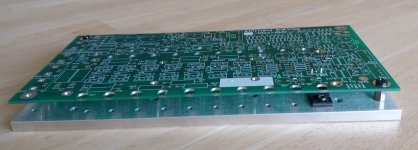
By bolting everything in place before soldering the TO-220 leads, they're in a stress-free position. If the tabs are unscrewed and the board removed, and later replaced, everything still lines up, without stress. The leads are bent 0.70 inches from the tab hole, which is 0.2 inches = 5 mm from the body. As described, grab in this 5mm region with your long-nose pliers, and bend beyond that point w/o stressing the package.
As for amplifier stability, given the alarming 10MHz bandwidth and 1 kV/us slewing, this design is remarkably stable, and load tolerant. The amplifier has only one primary pole. I credit the Tektronix engineer's design (They had > 50MHz bandwidth and 2000V/us slew rate), which we dissected and wrote about in detail, in the x-Chapter section draft text, included on DropBox. They simply reduce the open-loop gain with a pot on the summing junction, until the amplifier's feedback is optimal. Crude but effective. The amplifier is inherently linear and distortion free, but without employing excessive amounts of negative feedback. Other than their high-frequency loop-gain reduction scheme, it doesn't have any additional compensation components.
I'm enthusiastically on-board with everything you've said, except I don't think I agree that there is any such thing as "excessive amounts of negative feedback". There certainly does exist "instability" and there certainly exists circuits that are difficult to stabilize without greatly reducing bandwidth.
But the world does successfully build and use gigantic amounts of negative feedback, all day every day. Here is a five dollar opamp whose open loop gain is 300dB typical, 200dB worst case; it's stable at gains of 20dB or more, meaning it has 280dB of feedback. That's not excessive for these engineers: LINK
But the world does successfully build and use gigantic amounts of negative feedback, all day every day. Here is a five dollar opamp whose open loop gain is 300dB typical, 200dB worst case; it's stable at gains of 20dB or more, meaning it has 280dB of feedback. That's not excessive for these engineers: LINK
Thanks for your point, Mark, I agree completely. It's not unusual for amplifiers to have in excess of 120dB of negative feedback at DC and low-to-mid frequencies. I'm referring to the level of loop gain and negative feedback, mostly above 1MHz, as the amplifier approaches its 10MHz capability limits. Rather than add zeros and other such stuff, as we like to do, to tame the loop-gain phase shift, the Tektronix engineer's approach was to simply reduce the loop gain. This is probably one of the reasons the amplifier is well behaved at its high-frequency limits.
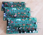
Boards, mounting plates and DC-DC converters available
This Monday the 3rd of June I will get sets of DC-DC converters for Winfields AMP-70, courtesy Mr. Hill.
I had the PCBs and the mounting plates delivered earlier, so now there are complete sets of the stuff that's not easily sourced.
Several people have reserved sets but I still have some available.
Complete set of PCB, mounting plate and 3 DC-DC converters, euro 25 plus shipping at cost. A pair is euro 45 + shipping.
Send me your shipping address via PM and I will calculate shipping, will be tracked lowest cost.
I will start putting the power supply system together next week and will report any issues here and on my website Winfield Hill's AMP-70 - Under Construction | Linear Audio NL
A fun project that will result in an absolutely unique amplifier!
Jan
Attachments
Yes sorry, I updated the title after posting the link.
Winfield Hill's 100W, 10MHz, 1000V/uS AMP-70 | Linear Audio NL it is.
BTW, The 3 DC-DC converters in the package are on the amplifier board, see the BOM. They increase the supply voltage for the pre- and drivers so the output stage can be driven to the main supply voltages.
Jan
Winfield Hill's 100W, 10MHz, 1000V/uS AMP-70 | Linear Audio NL it is.
BTW, The 3 DC-DC converters in the package are on the amplifier board, see the BOM. They increase the supply voltage for the pre- and drivers so the output stage can be driven to the main supply voltages.
Jan
Last edited:
I now have the BOM and Known Issues as live documents on the web site:
Winfield Hill's 100W, 10MHz, 1000V/uS AMP-70 | Linear Audio NL
Starting the proto build, will keep those doc updated as I go along. Another diy adventure!
Jan
Winfield Hill's 100W, 10MHz, 1000V/uS AMP-70 | Linear Audio NL
Starting the proto build, will keep those doc updated as I go along. Another diy adventure!
Jan
Drew first blood today. Slowly turned up the supply to +/-30V, that's max with my lab supply. No load. Current draw about +/-300mA + 350mA for the DC/DC converter, which gets fairly hot. Everything else seems normal, no magic smoke.
Unloaded output (1 output pair) looks OK, undistorted 1kHz. Gain about 10x.
And, as is customary at first switch-on ;-), low level oscillations, about 200mV pk-pk, about 6MHz.
My +/-50V/10A supply sits in the basement and weights about 100 kilos. Looking forward to lug it up 😡
Jan
Unloaded output (1 output pair) looks OK, undistorted 1kHz. Gain about 10x.
And, as is customary at first switch-on ;-), low level oscillations, about 200mV pk-pk, about 6MHz.
My +/-50V/10A supply sits in the basement and weights about 100 kilos. Looking forward to lug it up 😡
Jan
Drew first blood today. Slowly turned up the supply to +/-30V, that's max with my lab supply. No load. Current draw about +/-300mA + 350mA for the DC/DC converter, which gets fairly hot. Everything else seems normal, no magic smoke.
Unloaded output (1 output pair) looks OK, undistorted 1kHz. Gain about 10x.
And, as is customary at first switch-on ;-), low level oscillations, about 200mV pk-pk, about 6MHz.
My +/-50V/10A supply sits in the basement and weights about 100 kilos. Looking forward to lug it up 😡
Jan
Yes it is interesting indeed, do you thing you can get 1000V/us slewrate with load connected and get rid of the oscilation?
Happy building
- Home
- Amplifiers
- Solid State
- Winfield's 100W DC-10MHz 1000V/us amplifier