Whew. Nice, but it looks very expensive - I can see why you rather prefer to go with a fast amp.
It's 800 euros in Europe. Your nx won't be much cheaper, all counted ;-)
Jan
It's 800 euros in Europe. Your nx won't be much cheaper, all counted
The second one will be inexpensive; it's the first article of a new project that's terribly costly.
Did you build that one? Care to show?
Jan
No, I haven't build that one yet but construction is being prepared - also for eventual use of 4 ohm speakers (sim predicts ~ 50 ppb THD / 200W / 20 KHz / 4 ohm). However it needs a power supply that can be run from the UPS of the computer (frequent power cuts here) so must have an acceptable PF and soft start. Parts of the project will be shown when working as expected.
Time to resurrect this thread!
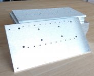
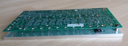
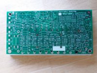
I have ordered PCBs for this amp, and have some mounting plates milled as well. As you may remember, this board mounts about 20 TO-220 devices from the bottom and they mount on an aluminum plate in threaded holes. The complete module can then be fixed to a chassis or heatsink, see attached pictures.
Since this is a pretty complex project with inputs from several parties, I have set up a separate webpage to collect all pertinent info as the projects moves to completion.
There are some spare boards and spare mounting plates, and if you are interested in a set or in a PCB, let me know.
Jan
Attachments
What beautiful work! Congratulations, Jan.
I imagine it might be difficult and painstaking to bend the leads of all twenty TO-220s exactly the same, then bolt them to the mounting plate, then thread the PCB's drill holes down onto the sixty (!) legs sticking up in the air. Is that the build sequence you will use?
Maybe another way is to bend the transistor leads, fit them into the PCB without the mounting plate, and then secure each one in position using some sort of temporary adhesive. Now apply the mounting plate and, one transistor at a time, remove the adhesive and bolt the transistor body to the mounting plate. When all 20 are bolted in, begin soldering the leads.
mounting the TO-220 parts on PCB is easy
Here's my answer to Jan, on March 7th,
"Correct, the TO-220 transistors are mounted underneath, and there's a hole in the PCB for your screwdriver. One of the images in the photos folder shows a side view, TO-220_side.JPG
[DropBox folder, explore:
Dropbox - AMP-70_DIY - Simplify your life ]
IIRC, this is the assembly procedure. First you measure and bend the TO-220 leads 90-deg upwards [all three pins at the same 0.70-inch distance], and insert all 20 transistor leads into the PCB holes. Then with the PCB facing bottom up, showing the transistor bottoms, you place the long machined heatsink bar plate over, and flip the whole affair. Next you install a few of the 0.375 spacers, and align the board and transistors to their holes. Then use a tweezer or longnose to temporarily install the TO-220 tab screws. As you screw everything down, you can tweak angles. Next, solder the TO-220 leads sticking out the top of the board.
At this point you can remove the tab screws and separate the assembly. The PCB can be further reworked and the heatsink plate is readied for assembly with the rest of the other two heatsink plates. BTW, the Intel D98510-001 heatsink is readily available (even tho the servers they were used in are long discontinued), but you want to be sure to get the version with a mounted fan, should be about $20 each. Intel's standard fan is good, it has a built-in speed control depending on heatsink temperature. If your chassis assembly doesn't give this fan access to outside air, you'll need to add another fan to ventilate the box."
I later responded to a Q about that the middle TO-220 pin being angled out. As you insert the MOSFET leads, and progress, it simply angles properly on its own. The triangle pattern was intentional, to allow for standing up TO-220 or TO-126 parts, etc, topside, with clip-on heatsinks. If the pins are in a straight row, the leads can bend (and break) at some point.
Thanks for the detailed explanation, Win! Using gravity instead of adhesive is a darn good plan -- D'oh. I imagine the spring tension from the slightly unequal angles of bent legs, helps to hold the transistors in place while you're lining up the mounting plate and flipping the whole assembly over.
Win's method is a good way to do it. I have done something similar in another project. If you insert the transistors from the bottom, you can bend two of the protruding pins slightly, 30 degrees or so, in opposite directions so they can't fall out. That is usually enough to hold the devices in place while you turn over the assembly.
When you get ready to solder, bend the pins back straight again so that they can settle without stress.
That is the most important thing in either case: make sure the devices are firmly screwed onto the mounting place and the PCB is also screwed onto it at the 4 corners, and the pins are settled, before soldering, to avoid any mechanical stress.
Jan
I use Winfield’s approach, ie mounting from the bottom, in all my commercial amps and on the e-Amp. The PCB acts as a torque spreader. I have never had any problems with it.
Re bending transistor leads: place your pliers closet to the transistor body and bend the leads, not the other way around.
Having worked in power semiconductors professionally for 10 years, I can tell you stressing the package/lead interface is a bad idea and results in long term reliability issues (I worked in auto - so millions of power devices per month in a tough under-the-hood environment!)
Do you have any references on the need to eliminate stress in leads before soldering?
No, except common sense ;-) . If you solder the pins and then proceed to screw the case to a heatsink it's very easy to put (a lot of!) stress on the leads and the solder joints. That can't be a Good Thing.
Jan
Check this out, it may help 🙂
Frans as far as I can see this addresses deformation of the case rather than putting stress on the leads/solder joints.
Jan
Re bending transistor leads: place your pliers closet to the transistor body and bend the leads, not the other way around.
Yes!
Jan
I am in contact with a group at a university in Berlin who have been building this amp also. They documented their findings, and I need to translate that in English and post.
Jan
Jan
No, except common sense ;-) . If you solder the pins and then proceed to screw the case to a heatsink it's very easy to put stress on the leads and the solder joints. That can't be a Good Thing.
Jan
Stress is always a bad thing 🙂 There was a application note about bending legs on plastic power devices specifically (when I worked for Motorola), but I can not find if, I did find AN1040 (above). Any way the short answer is, there should bo no stress before soldering, any stress left (under thermal movement caused by expanding and contraction of materials) may cause to (or lead to) failure of the device's case or the soldering.
As Bonsai notes, clamp the leg neer to the device (plastic body) and then bent the leg (sticking out free), e.g. do not created stress where the lead is entering the plastic device body.
Last edited:
Frans as far as I can see this addresses deformation of the case rather than putting stress on the leads/solder joints.
Jan
Yes, I know, I can not find the specific AN about lead treatment (sorry).
- Home
- Amplifiers
- Solid State
- Winfield's 100W DC-10MHz 1000V/us amplifier