There is a systematic error here, Hans. I cannot imagine what that is, but it cannot be real for reasons set out previously.But now it comes: When making the same speed step with a mono signal, level deviation becomes zero !!!
So a stereo signal seems to increase its level with the sqrt of the speed increase factor whereas mono has a direct proportional relation.
It's a pity Faraday doesn't live anymore, he could have helped us.
LD
There is a systematic error here,
Yes, I let the first track (3150Hz speed calibration tone) on the Adjust + spin down freewheeling from 5kHz to 640Hz and saw no issues.
Hi LD,There is a systematic error here, Hans. I cannot imagine what that is, but it cannot be real for reasons set out previously.
LD
Read on, after this posting I discovered that it had to do with RMAA.
So I took this all back in #933.
Hans
In the meantime Maxim has already given a superfast reaction, and the problem seems to be solved.
I'm back again in business with RMAA.
Hans, can you inform us how the problem has been solved? (me too I am using RMAA)
George
Hi George,Hans, can you inform us how the problem has been solved? (me too I am using RMAA)
George
Problem solved, I did something wrong.
You can continue using RMAA without worries.
Hans
Thank you, George.Thanks Demian
I added Demian’s cartridges data into the previous diagrams from my measurements for comparison.
I admit I've lost track of the test jig/regime in play here, would you pls briefly outline?
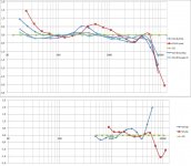
On the face of it, these results across a range of cartridge coils show strong f dependent loss / f dependent inductance which I suppose shows up as the coil impedance becoming more real at hf, especially above the audioband?
Generally in magnetics, there has to be a time derivative involved for there to be any action. Such as rate of change of flux, ie velocity. The effect of constant amplitude sine f sweep is that velocity increases directly with f (the derivative of sin(at) is a*cos(at).
Loss mechanisms that involve flux reversals also depend directly upon the derivative of number of reversals, ie frequency (reversals per second).
So magnetic loss mechanisms should have a direct f relationship as the lowest observable order. If two independent mechanisms apply, the lowest order should be f2.
So those graphs look plausible in principle, I think.
LD
I'm having trouble interpreting that post. If you are saying that the cartridge coils show the usual frequency response and resonant peak associated with a real world inductor then I agree.
What interests me is that we have an inkling of a credible mechanism for the midband droop in MMs that doesn't require jumping through the hoops of mech resonance in the audioband.
What interests me is that we have an inkling of a credible mechanism for the midband droop in MMs that doesn't require jumping through the hoops of mech resonance in the audioband.
Well cart coils should behave as real world inductors. I was trying to say some loss dmechanisms depend on rate of change of flux which is only a cousin of frequency. Also on level. So periodicity as in sine f isn't necessarily involved. Whereas some mechanisms are periodic such as LC resonance or hysterisis loss.I'm having trouble interpreting that post. If you are saying that the cartridge coils show the usual frequency response and resonant peak associated with a real world inductor then I agree.
LD
Scott,Yes, I let the first track (3150Hz speed calibration tone) on the Adjust + spin down freewheeling from 5kHz to 640Hz and saw no issues.
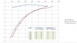
It took me quite some time to get results to within +/-0.5dB while performing this test.
I used the same methodology as before, and calculated the level curve, as well for a square law as for a direct proportional relationship between speed and level.
In the image below the two calculated curves are drawn, together with the measured curve.
Deviation of only +/-0.5dB from the calculated curve proves two things:
1) level is directly proportional to speed
2) the math used to predict this seems to be accurate.
Now I'm still faced with the problem why for all the other measurements, six in total, level has to be corrected by exactly 10*log(speed change).
Hans
Attachments
I was trying to say some loss dmechanisms depend on rate of change of flux which is only a cousin of frequency. Also on level.
LD
Gotcha, although based on Hans last sims we may have some more significant things to correct before we tease out level issues that muddy the waters.
Where there is f dependent roll-off that is fertile ground for level sensitive response when looking at sine waves. 'There be treasure' as the old adventure game might say😉
LD
LD
What interests me is that we have an inkling of a credible mechanism for the midband droop in MMs that doesn't require jumping through the hoops of mech resonance in the audioband.
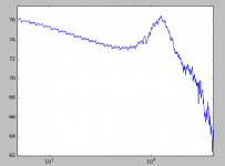
Speaking of which, I've been playing with my code to do the frequency sweep as a single huge transform. The regular wiggles here at the low end are warp and eccentricity, at the high end it seems that surface noise starts to hurt (there is no averaging). This is 500Hz to 40kHz (40-48kHz was mostly noise), arbitrary dB reference. This is the CV sweep no equalizations.
Attachments
I checked in the most detailed way my calculations, but after all in the end the mysterious discrepancies in level versus rpm, has to be fully accounted to RMAA.
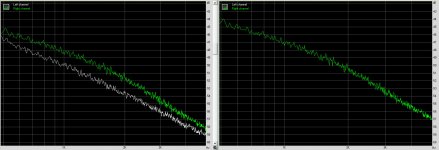
The left side of the Image below has both R channels mixed of 33 1/3rpm and 60.75rpm stereo recordings merged into one stereo track.
On the right side is only the R channel of the original 60.75rpm stereo track.
Both green lines are exactly the same in shape but not in level, although they are one and the same.
Ergo, RMAA is capable of showing the perfect shape of a spectrum, but is not exact in showing the level, sorry George, I'll have to come back on my earlier remark.
I'll try to communicate this again with Maxim Liadov.
I have now completed my measurements, beginning with the 45rpm CH Precision record at 33 1/3 and at 60.75rpm, with Pink Noise.
Next I have measured the 33 1/3 Adjust+ record with Pink Noise at 45rpm and at 60,75rpm.
From the same record I have measured a frequency sweep from 20Hz to 20kHz at 45rpm, and as a last step I have measured a track only modulated on one channel, with the same sweep.
Results with these sweep signals are even closer to the predicted level, almost to within +/-0.25dB.
In all cases, the result is that deviation from the calculated curve versus the measured curve is within +/-0.5dB up to 20kHz.
One thing is remarkable: when speeding up a record, levels above 20kHz are becoming louder as expected in all tests, PN and Sweep, and going the other way down from 45rpm to 33 1/3rpm, the high frequencies are dropping in level vs expectation. No idea why.
I see no further reason with this Cart to add any additional correction for constant velocity errors and that was the primary objective of these tests.
Hans
Attachments
I had actually wondered with these 500Hz to 40kHz CV sweeps how high you get before the SNR drops horribly. Your graph is interesting as it shows the midrange dip and the treble peak (albeit that with grado TADTS* applies). But there is no sign of a transmission line resonance series there.Speaking of which, I've been playing with my code to do the frequency sweep as a single huge transform. The regular wiggles here at the low end are warp and eccentricity, at the high end it seems that surface noise starts to hurt (there is no averaging). This is 500Hz to 40kHz (40-48kHz was mostly noise), arbitrary dB reference. This is the CV sweep no equalizations.
*They All Do That Sir, a common british brush off to customers complaining about things. In audio describes Linn customer care particularly. Bugatti was particularly bad at this 😀
This I assume is your rather nice Benz?
I see no further reason with this Cart to add any additional correction for constant velocity errors and that was the primary objective of these tests.
Yes, true. I can only speak for this Cart, but I hope it is valid for most carts. 😀I had actually wondered with these 500Hz to 40kHz CV sweeps how high you get before the SNR drops horribly. Your graph is interesting as it shows the midrange dip and the treble peak (albeit that with grado TADTS* applies). But there is no sign of a transmission line resonance series there.
*They All Do That Sir, a common british brush off to customers complaining about things. In audio describes Linn customer care particularly. Bugatti was particularly bad at this 😀
This I assume is your rather nice Benz?
Hans
But there is no sign of a transmission line resonance series there.
There is a funny bump at ~9K that the PN tracks had, no idea what that could be. Transmission line effects open up the door for non-minimum phase and I'm not sure how this would play into the Hilbert transform algorithms I am using (I'm also not that keen on making this an academic project). But you are right up to 7k you can count the revolutions (24 sec / decade, 14 bumps 500-5k or 1.71 sec each by eyeball, too close not to be that.). Take them out and the plot is dead flat to a small fraction of a dB.
Last edited:
If they exist, as I venture they should, they are strongly not minimum phase. Mechanical TLs are dispersive. A practical example is railway lines where one hears hf content of an arriving train long before lf.Transmission line effects open up the door for non-minimum phase
That said, by calculation, there's no real action for cantilevers until the upper mids perhaps >4kHz or so.
LD
Last edited:
To recap slightly and test my understanding: there is conflicting evidence on this thread as to whether, at a constant realistic applied signal sine amplitude, measured coil inductance typically varies with f in the audioband and immediately above it.
Is the above a true statement, and if so to what do we attribute the discrepancy between results?
LD
Is the above a true statement, and if so to what do we attribute the discrepancy between results?
LD
'Inductance' in this case doesn't parse with me. It is a complex impedance that is poorly modelled. Hans model is a bit more complex than the Rod Elliot one and seems to hind that we can explain the midband dip and HF rise entirely with the cartridge model. Post 885 is the pertinent one here.
We need more measurements of course to make sure we are not hammering the model to fit the data, but I see this as a loose end that really needs a good tug.
We need more measurements of course to make sure we are not hammering the model to fit the data, but I see this as a loose end that really needs a good tug.
Last edited:
- Status
- Not open for further replies.
- Home
- Source & Line
- Analogue Source
- Cartridge dynamic behaviour