How do I use it? The areas update each other.
Hi Mårten,
See CHANGE 1 in Post #9152 linked below, for details.
https://www.diyaudio.com/forums/subwoofers/119854-hornresp-916.html#post5690559
Kind regards,
David
Hi David - the resize wizard seems to not let me downscale below unity and says "1.01" as minimum size. Did I goof up something ?
the resize wizard seems to not let me downscale below unity and says "1.01" as minimum size.
Hi freddi,
The Resize Wizard checks to see that all the re-scaled parameter values are within the standard permitted input limits. If they are not, then the error message will be generated. If you would like to post a copy of the record you wish to rescale, I can identify for you which parameter value is causing the problem.
Kind regards,
David

oh - I must had messed up something - don't see well
Hi freddi,
Thanks for posting the record.
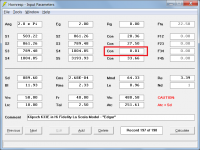
You didn't mess anything up - the problem parameter value is the 0.01 cm length of segment 3.
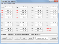
If the Resize Factor is less than unity the re-scaled value of L34 becomes less than 0.01, the permitted minimum limit, which is why the error message is being generated. To get around the problem, use the recently-added stepped segment functionality to avoid having to include the 0.01 cm length segment, as shown in Attachment 2.
Kind regards,
David
Attachments
Many Thanks !
Hi freddi,
Not a problem 🙂.
Just to complete the picture, before the stepped segment feature became available the way around the problem would have been to simply increase L34 from 0.01 to 0.10, to permit up to a ten-fold size reduction (with a ten-fold reduction, 0.10 would re-scale to 0.01, the minimum permitted value for L34).
Kind regards,
David
@David, is the driver simplified to a point or is it distributed along the horn?
For a traditional horn a point source is very close to reality for all frequencies.
For an offset driver construction, typically a MLTL or a TH, regarding the driver as a point source will be accurate at the bottom end. But when there is a pressure maximum passing the cone (frequency wise), the simulation will not be perfectly accurate.
Best regards
Mårten
is the driver simplified to a point or is it distributed along the horn?
Hi Mårten,
The driver (or equivalent composite driver in the case of multiple drivers) is modelled as a point source.
Kind regards,
David
Hi Mårten,
The driver (or equivalent composite driver in the case of multiple drivers) is modelled as a point source.
Kind regards,
David
Then may I suggest that you introduce a new mode where you simulate the (cone) driver as distributed along a line. It will not take just a weeks work though, but you don't have to change the gui at least 🙂
Thanks again for you excellent work David.
Best regards
Mårten
Then may I suggest that you introduce a new mode where you simulate the (cone) driver as distributed along a line.
Hi Mårten,
The driver diaphragm is modelled as a rigid plane circular piston. No allowance is made for frequency-dependent directional characteristics due to driver cone angle or cone material, or for changes in moving mass, acoustical impedance or radiated power caused by diaphragm resonance modes. Results at the higher frequencies would still be inaccurate even if the diaphragm was modelled as a distributed straight-line source because each point source in the array would have a different frequency-dependent strength and phase. Not enough is known about the driver to enable these values to be calculated.
Kind regards,
David
Equation source?
I'm a student at Purdue (and a newbie on this forum). I'm in a class which teaches enclosure basics, but I haven't tried to derive a horn formula myself. Is there a website or book that you based this program's code off of? I really like the program btw!
I'm a student at Purdue (and a newbie on this forum). I'm in a class which teaches enclosure basics, but I haven't tried to derive a horn formula myself. Is there a website or book that you based this program's code off of? I really like the program btw!
Is there a website or book that you based this program's code off of?
Hi steven3303,
The numerous models used in Hornresp are based on information gleaned from various sources, but a good place for you to start would be with the following two books:
1. "Acoustical Engineering" by Harry F Olson.
2. "Acoustics: Sound Fields and Transducers" by Leo L Beranek & Tim J Mellow.
(The very first version of the original precursor to Hornresp was based solely on information contained in Harry Olson's book).
Kind regards,
David
I can wholeheartedly recommended both the above books. Olson's book can be a bit hard to find, but Beranek and Mellow is currently available and contains lots of useful horn and enclosure info, including how to calculate frequency response etc.
And if all goes well, there will be a book about horn speakers published sometime at the end of this year 😉
And if all goes well, there will be a book about horn speakers published sometime at the end of this year 😉
And if all goes well, there will be a book about horn speakers published sometime at the end of this year 😉
I hereby preorder a copy 🙂
Hello all,
I discovered horn resp a few times ago, its really amazing but i'm missing few informations about the functionning.
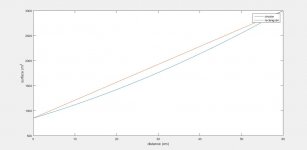
I assume that the shape of the expansions are made for circular horns. However, a lot of people uses hornresp to simulate some low frequency cabinets. In the case of a cabinet of fixed width with a straigth expansion on the other axis, only one dimension is expanding. This leads to a straigth expansion of the surface (theorically corresponding to a parrabolic expansion). However, most of the simulations that i see people doing uses conical expansion (which theorically corresponds to a squared expansion of the surface). I didn't find any informations concerning hornresp's expansions laws. I have linked a simulation of the expansion of a fixed width cabinet with a straigth expansion along the other axis and a theorical conical expansion. It appears that there is effectively a difference between the 2.
Does someone knows what expansion to use in that case?
Thanks in advance
I discovered horn resp a few times ago, its really amazing but i'm missing few informations about the functionning.
I assume that the shape of the expansions are made for circular horns. However, a lot of people uses hornresp to simulate some low frequency cabinets. In the case of a cabinet of fixed width with a straigth expansion on the other axis, only one dimension is expanding. This leads to a straigth expansion of the surface (theorically corresponding to a parrabolic expansion). However, most of the simulations that i see people doing uses conical expansion (which theorically corresponds to a squared expansion of the surface). I didn't find any informations concerning hornresp's expansions laws. I have linked a simulation of the expansion of a fixed width cabinet with a straigth expansion along the other axis and a theorical conical expansion. It appears that there is effectively a difference between the 2.
Does someone knows what expansion to use in that case?
Thanks in advance
Attachments
I can wholeheartedly recommended both the above books. Olson's book can be a bit hard to find
+1
I presume ya'll mean the one I have, which is now available online: http://cyrille.pinton.free.fr/electroac/lectures_utiles/son/Olson.pdf
GM
+1
I presume ya'll mean the one I have, which is now available online: http://cyrille.pinton.free.fr/electroac/lectures_utiles/son/Olson.pdf
GM
There can be only One (Olson).😀

Folks,
So I have produced a Tapered TL that has acceptable size, F3, and TL length for my drivers.
Question: All I see in the Loudspeaker Wizard is the cross section area of each segment, but the schematic shows system volume. Where does it get the internal width from for the volume calculation?
Second Question - so my S1 has a particular cross section area, and it has the shape of a trapezoid. I know the length = L12. Is there any way to determine the dimensions for the large end and small end of S1?
Apologies if this is remedial geometry.
Thanks in advance.
Last edited:
There can be only One (Olson).😀
True TTBOMK, but I have all my major books in storage and couldn't remember if this was the latest version, so with as many 'senior moments' I've been having lately........... 🙁
GM
- Home
- Loudspeakers
- Subwoofers
- Hornresp