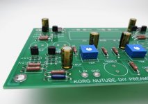
Trimmer pots and power resistors next.
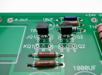
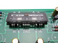
Now stuff all the Q2. Remember the R1 resistors are matched to these particular transistors, do not mix your Q2 and Q1 together!
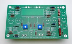
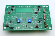
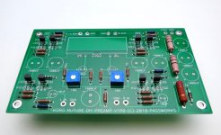
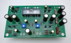
PCB should look like this now.
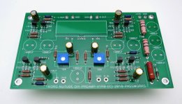
With your Q2 installed on the PCB, install the four Q1
Now mount the 10uF capacitors
Attachments

Last edited:
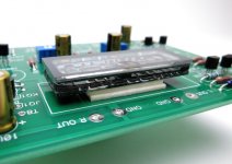
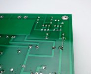
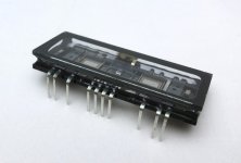
The NuTube has pins on one side.
Those pins will attach into these holes. This is not particularly sturdy if left by itself, Nelson suggests a small amount of hot glue to hold the device, which will work beautifully. I have a roll of two-sided foam tape and use that to similar effect.
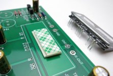
Two-sided foam tape
I cut two small rectangles, place one on the PCB as shown, peel the tape;
Place the second one atop the first,
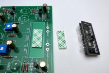
Align the PINS FIRST in the holes before peeling the tape, then attach the NuTube and solder the pins.
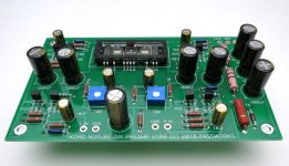
Mount the large can capacitors.
If you have the "V1R0" board, attach jumper as shown. ALL other revisions DO NOT NEED THIS JUMPER
Attachments
-
 IMG_0644.jpeg60.7 KB · Views: 1,564
 -
 IMG_0645.jpeg74 KB · Views: 1,560
 -
 IMG_0646.jpeg82.9 KB · Views: 1,566
 -
 IMG_0647.jpeg49 KB · Views: 1,541
 -
 IMG_0642.jpeg73.2 KB · Views: 1,546
 -
 IMG_0641.jpeg77.4 KB · Views: 1,561
 -
 IMG_0640.jpeg45.6 KB · Views: 1,568
 -
 IMG_0639.jpeg78.1 KB · Views: 1,559
 -
 IMG_0638.jpeg50.7 KB · Views: 1,555
Last edited:
I'm used to the PCB having components labeled as R1,R2...rather than their values. What's the reasoning behind the change. I haven't stuffed the B1 with Korg yet, but I'm thinking I like the old way better.
...that's the way Nelson laid this one out. It's a simple enough board that you can figure it out looking at the schematic.
The best of both worlds would be to have the values inside the silk outline and the position name next to it.
The best of both worlds would be to have the values inside the silk outline and the position name next to it.
Jim,
What is the thickness of the 2 layers of 3M double sided tape you used under the nu Tube?
I have some 3mm thick anti vibration Sorbothane sheet I will use for that position.
Then I will mount the PCB into the enclosure on small M3 (3mm) anti vibration mounts made from very durable rubber - these have a 3mm stud one end and a 3mm thread the other. They are used a lot in drones and remote controlled helicopters.
Once finished I will then stick on some very compliant Acoustic feet - Audio isolation feet for the bottom of the enclosure - these are 30mm dia and around 8mm thick.
Overall with these 3 items this should give maximum isolation for the Nu Tube from external vibration and noise.
I'll make a real guide once the chassis is available.
Do you know which chassis and dimensions will be made available for this preamp? Will it include RCA connectors, a DC power connector and knobs too? I will hold off on those items if a diyAudio Store chassis kit is in the works.
Thanks
Gary - 2-3mm max. Thin enough that the pins stick through the PCB and are easy to solder, but don't need trimming.
Your plan for isolation sounds good. 🙂
Rich - Probably 230 x 170 x 1U. There will be kit options for all the parts. I have NO idea what the timeline will be, you might as well just buy the parts and build it from scratch, it's a very simple layout and you'll love the NuTube. 🙂
Your plan for isolation sounds good. 🙂
Rich - Probably 230 x 170 x 1U. There will be kit options for all the parts. I have NO idea what the timeline will be, you might as well just buy the parts and build it from scratch, it's a very simple layout and you'll love the NuTube. 🙂
I have some 3mm thick anti vibration Sorbothane sheet I will use for that position
Hi Gary,
I used the same Sorbothane sheet, cut a piece for under the NuTube and a large piece under the entire board. Works like a charm!! No microphonic noises
at all 😀
Last edited by a moderator:
I've been using my xmas B1 nutube as a headphone amp as well as a pre....(60 Ohms) HD25-SP IIs. I've made no adjustments to the circuit at this stage for the headphone use.
It sounds quite superb....IMO, so you may not need to look any further for a quality phone amp..🙂. If you were looking for one.
Filament dissipation is no more than 12 mW as per manufacturer's sheet. I would assume power output would be about a third that, if other power tubes are any indication i.e. 4 mW. Output impedance per NP's spec would be 140 ? ohm. So, you need sensitive headphones and high impedance types probably wouldn't work.
I used a headphone adaptor on the outputs when I judged that things were working. One was 30 ohms and sensitive, the other was 80 ohm and very sensitive. I thought they sounded great. To get some current with other headphone types, coupling with Op Amp to make a hybrid would probably be suggested.
Thanks for those replies Jim and Vunce - if you are going to do a job then do it right and all will be good I say.
cjfrbw - You're not actually listing to the nuTube, but instead the output buffer... 🙂. With it's 392K plate resistor, the NuTube can't even drive cables very well, hence why it needs something between it and the rest of the world. The Jfet buffer adds current (enough, obviously, for some headphones) and doesn't editorialize at all.
Last edited:
"Depending on the Jfets, the buffered output impedance of the preamp is 140 ohms to 170 ohms (including the 100 ohm output resistor)."cjfrbw - You're not actually listing to the nuTube, but instead the output buffer... 🙂. With it's 392K plate resistor, the NuTube can't even drive cables very well, hence why it needs something between it and the rest of the world. The Jfet buffer adds current (enough, obviously, for some headphones) and doesn't editorialize at all.
I suppose a little high-ish for standard 30 to 100 ohm dynamic headphones.
The ones I used got louder than I wanted with an ipod input (less than 1 V?) so there seems enough power for these types of headphones. I don't know what the impedance mismatch might do for frequency balance etc.
I don't think the NuTube is a power house, but a tech type could weigh in to give more specifics on power output for this particular device.
My Nutube version from the diystore is now up and running and all is well.
I have a question about measuring T7-8 - I have chosen about 9.5V and should be in the “Positive phase range”. What does that mean - do I not have to swap the speaker wires if I want correct please?
What is the expectet lifetime of the Nutube in this circuit?
I have a question about measuring T7-8 - I have chosen about 9.5V and should be in the “Positive phase range”. What does that mean - do I not have to swap the speaker wires if I want correct please?
What is the expectet lifetime of the Nutube in this circuit?

Thanks, I guess that should be enough😉
Jim / 6L6, another fantastic building guide and ... God is it clean!
Thanks again for sharing all this
Claude
Thanks again for sharing all this
Claude
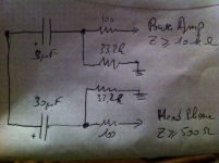
While in the train, on a back of an enveloppe (sorry for low quality and low brain), I guess another silly idea of mine, but could perhaps the expert give their opinion?
Problem is you want a high quality output cap driving into the power amp, that one has to be as small as possible to reduce cost and help implantation.
On the other hand, as "additional function", I understand perhaps not best but let's assume the B1 Nutube can drive an efficient 600R headphone to reasonable listening level... you want another exit in parallel, which is easy to pick on the board, but you need a much bigger output cap to avoid low frequencies cut off... as this is just a B plan, you could leave with a normal quality electrolytic and a reasonable low Fc.
So as per attachement, what about splitting their ways just before the output cap and having 2 different ways with 2 output caps: low value HQ output cap to drive into the power amp, normal quality higher value to drive into the HP?
Stupid boom paralleling caps... or a possible solution?
Thanks in advance to the experts
Claude
Attachments
- Home
- Amplifiers
- Pass Labs
- B1 with Korg Triode