Thanks to all the kind contributors here I digged into the schematic and a lot of unknown concepts to me (cathode bypass, collector decoupling)... and learned a lot -no wonder starting from scratch 🙂. Many thanks, that's entertaining!
I undertsand now why some caps that don't seem to be in the critical sonic path are in fact... and that the choices of course wisely advised by Papa are best followed and left alone! Clever cooking of course...
I have though one last question, if you guys don't mind.
To my knowledge no one yet mentioned if this pre could drive a high impedance headphone. Of course, given the high pre-output impedance I was only thinking of a (highish) nearly constant 600 Ohm impedance headphone. Of course, if that's the case, the last output cap would probably need to be upgraded from 10uF to say 22uF or whatever to avoid low frequency cutting (as said I did my homework)
I am not looking for a quality phone amp, more "an OK monitoring simple add-on solution", in parallel to the "regular outputs driving the power amp" (say with some 100R line decoupling to avoid interferences between these, and both would anyway never be used at the same time)
Silly idea or feasible? Headphone is Beyerdynamics DT990 from several decades, I am not listening loud... felt worth asking, sorry if stupid thought
Many thanks again
Claude
of course that you can try , even use it if you like it
nothing's gonna burn in flames , no worries
nothing's gonna burn in flames , no worries
Thanks to all the kind contributors here I digged into the schematic and a lot of unknown concepts to me (cathode bypass, collector decoupling)... and learned a lot -no wonder starting from scratch 🙂. Many thanks, that's entertaining!
I undertsand now why some caps that don't seem to be in the critical sonic path are in fact... and that the choices of course wisely advised by Papa are best followed and left alone! Clever cooking of course...
I have though one last question, if you guys don't mind.
To my knowledge no one yet mentioned if this pre could drive a high impedance headphone. Of course, given the high pre-output impedance I was only thinking of a (highish) nearly constant 600 Ohm impedance headphone. Of course, if that's the case, the last output cap would probably need to be upgraded from 10uF to say 22uF or whatever to avoid low frequency cutting (as said I did my homework)
I am not looking for a quality phone amp, more "an OK monitoring simple add-on solution", in parallel to the "regular outputs driving the power amp" (say with some 100R line decoupling to avoid interferences between these, and both would anyway never be used at the same time)
Silly idea or feasible? Headphone is Beyerdynamics DT990 from several decades, I am not listening loud... felt worth asking, sorry if stupid thought
Many thanks again
Claude
There are lots of headphone PCBs on eBay and elsewhere. Based on simple headphone amp ICs or more “advanced” designs. You could pop in the simplest of those especially if you quality sound requirements are not stellar.
A quick question on the 475R resistor on the Christmas board that I have. Can I use a 470R 0.125W resistor instead of 475R? Does the difference of 5R makes an impact as 475R is not a regular resistor easily available locally and I had to order them either from RSDELIVERS or some other overseas site.
Thanks
Thanks
answer to manniraj #1788
Hello manniraj,
shouldn´t make a big difference. If you buy a 475 Ohm resistor with a tolerance
of 1% it will be anywhere inbetween 472 and 477 Ohm (approximately).
I think Nelson Pass mentioned that 0.6 W resistors should be used?
But perhaps our Professor Nelson can answer this? Or anybody of the experienced members here. 😕
Greets
Dirk
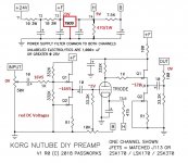
It looks like you need something with a higher wattage. Per Papa's document,
the 475 ohm resistor is across T4 and T5/T6. T4 should be at round 9.1V
and T5/T6 around 0.6V. The 8,5V drop works out to a bit over 0.15W.
So you'll definitely want something rated somewhat higher than that.
the 475 ohm resistor is across T4 and T5/T6. T4 should be at round 9.1V
and T5/T6 around 0.6V. The 8,5V drop works out to a bit over 0.15W.
So you'll definitely want something rated somewhat higher than that.
I am not looking for a quality phone amp, more,,,,
Claude
I've been using my xmas B1 nutube as a headphone amp as well as a pre....(60 Ohms) HD25-SP IIs. I've made no adjustments to the circuit at this stage for the headphone use.
It sounds quite superb....IMO, so you may not need to look any further for a quality phone amp..🙂. If you were looking for one.
Last edited:
That's very promising, thanks
How did you make the connection after the B1 Nutube output? Just in parallel?
What output cap have you been using, I guess the std 10uF might heva been a bit too low (bass cut?)
Many thanks!
Claude
How did you make the connection after the B1 Nutube output? Just in parallel?
What output cap have you been using, I guess the std 10uF might heva been a bit too low (bass cut?)
Many thanks!
Claude
A quick question on the 475R resistor on the Christmas board that I have. Can I use a 470R 0.125W resistor instead of 475R? Does the difference of 5R makes an impact as 475R is not a regular resistor easily available locally and I had to order them either from RSDELIVERS or some other overseas site.
Thanks
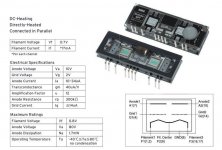
B1 Triode filaments heaters current need precise resistors 475R equivalent can be 470R+5R connected in series.
See extract about and why from FW article.
🙂 Best regards
Attachments

The difference between 475R and 470R is a bit more than 1%. This circuit will work fine with 5% tolerance resistors.
I wouldn't worry about it at all.
I wouldn't worry about it at all.
Max filament voltage = 0.8V optimal current = *17mA per chanel
Anyways, always check with multimeter the real resistor value before stuffing this PCB 😉
Anyways, always check with multimeter the real resistor value before stuffing this PCB 😉
Attachments
Last edited:
Right! I would not worry much about the 475 Ohm resistor.
I had more problems with the 9.1V Zener. I bought 10 of them and they turned out to be between 9.41 and 9.7 V (checked with two DMM)
This is a bit much and the filament current is a over 18ma
Consequently it might be better to check the Zeners first and then choose the right value for the resistor...
Last edited:
Oops my typo. Thanks ZM17mA
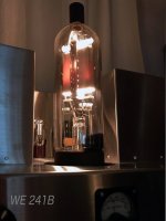
Just say tiny Korg filament 17mA are not that robust compared to vintage power 241 tube made by Western Electric 🙂
Attachments
Right! I would not worry much about the 475 Ohm resistor.
I had more problems with the 9.1V Zener. I bought 10 of them and they turned out to be between 9.41 and 9.7 V (checked with two DMM)
This is a bit much and the filament current is a over 18ma
Consequently it might be better to check the Zeners first and then choose the right value for the resistor...
@ Jostwid
Yup good point to keept filament current always in safe and optimal value 🙂 Thanks for sharing
Thanks guys let me find out if I can get a 475R with at least 0.6-1W range any of the resistors. I will also double check the 9.1v diode on my DMM before soldering.
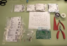
Stuffing a STORE style PCB
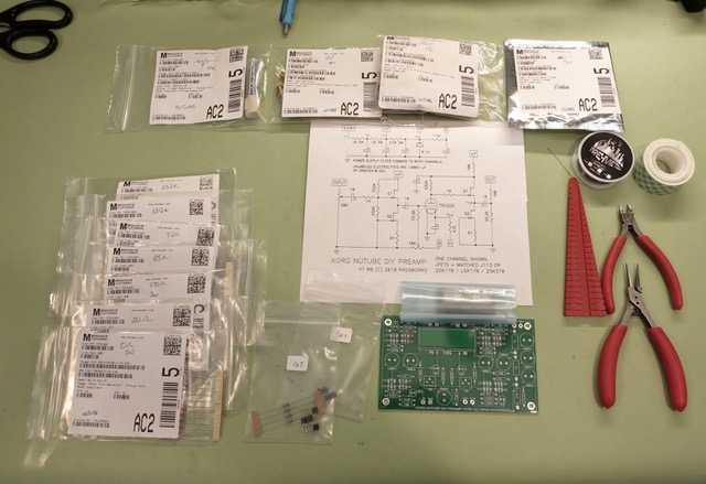
Gathering tools and components
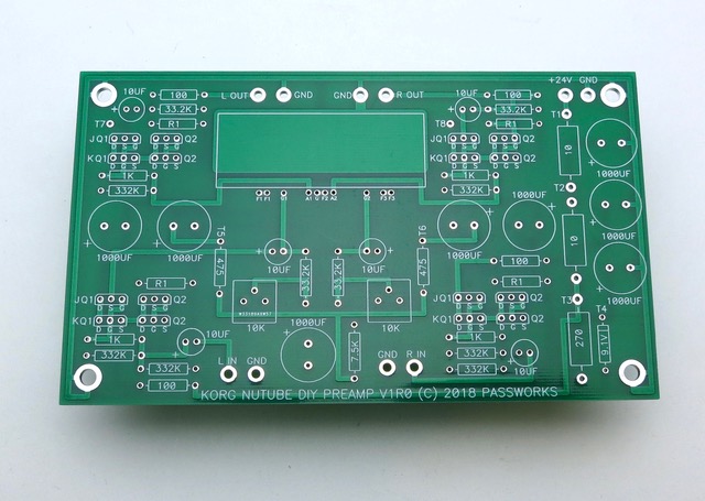
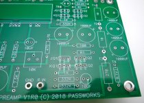
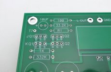
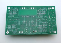
STORE board. (instead of XMAS board). This is the "R0" that has the need for the jumper on the back as shown in Nelson's guide. Later revisions will not need it.
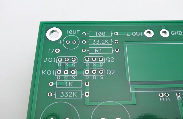
STORE version has 2 sets of pads to accommodate Toshiba/Linear Systems Jfets, marked "KQ" and Farchild Jfets marked "JQ"

.
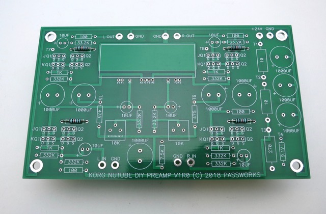
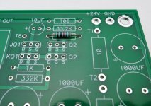
There are 4 locations for resistors all marked "R1", this is for the matched resistors that mate to the Q2's - these resistors are included with the kit. We will stuff them first

.
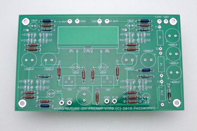
The rest of the small resistors and the Zener diode should be stuffed now.
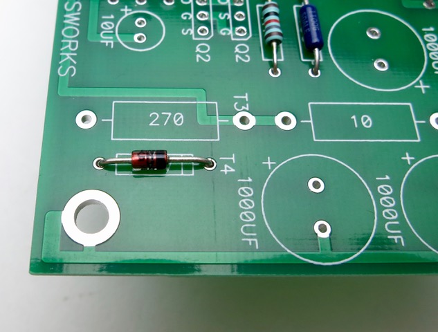
Note that the zener diode has a black line that should be on the same side with the line on the silkscreen
Gathering tools and components
STORE board. (instead of XMAS board). This is the "R0" that has the need for the jumper on the back as shown in Nelson's guide. Later revisions will not need it.
STORE version has 2 sets of pads to accommodate Toshiba/Linear Systems Jfets, marked "KQ" and Farchild Jfets marked "JQ"
.
There are 4 locations for resistors all marked "R1", this is for the matched resistors that mate to the Q2's - these resistors are included with the kit. We will stuff them first
.
The rest of the small resistors and the Zener diode should be stuffed now.
Note that the zener diode has a black line that should be on the same side with the line on the silkscreen
Attachments


Last edited:
- Home
- Amplifiers
- Pass Labs
- B1 with Korg Triode