Tried out some magnets
Regarding using the magnets on the Nutube:
I was intrigued by a couple of the posts about putting the magnets on the nutube and it changing the distortion. I ordered up some magnets because I can never have enough super strong magnets to play with - Amazon Link
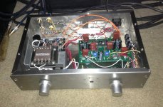
Since I used a carrier PCB for the Nutube it was super easy to put a magnet on the backside.
Upon doing so the sound was noticeably different, not saying better or worse. But when I measured the voltage on T7 and T8 it had changed significantly, like around 15v or 16v. If I moved the magnet slightly then the voltage could go up as high as 22V.
I fixed the magnet is place, then dialed the pot back to 11.2v where is where I had it before, then measured it using the same crappy USB soundcard I have and the results were pretty similar to when there was no magnet.
So my my totally noob and unqualified observations that should be taken with a grain of salt, the changes seemed more to a voltage change than anything else. I don't have the equipment or knowledge to do a proper measurement of distortion, just a basic USB soundcard.
Another note - putting the magnet on top of the Nutube had a similar effect to putting it on the bottom. That might make it easier for others to try.
Regarding using the magnets on the Nutube:
I was intrigued by a couple of the posts about putting the magnets on the nutube and it changing the distortion. I ordered up some magnets because I can never have enough super strong magnets to play with - Amazon Link
Since I used a carrier PCB for the Nutube it was super easy to put a magnet on the backside.
Upon doing so the sound was noticeably different, not saying better or worse. But when I measured the voltage on T7 and T8 it had changed significantly, like around 15v or 16v. If I moved the magnet slightly then the voltage could go up as high as 22V.
I fixed the magnet is place, then dialed the pot back to 11.2v where is where I had it before, then measured it using the same crappy USB soundcard I have and the results were pretty similar to when there was no magnet.
So my my totally noob and unqualified observations that should be taken with a grain of salt, the changes seemed more to a voltage change than anything else. I don't have the equipment or knowledge to do a proper measurement of distortion, just a basic USB soundcard.
Another note - putting the magnet on top of the Nutube had a similar effect to putting it on the bottom. That might make it easier for others to try.
Last edited:
Interesting about the magnets. I am still in a Pass Labs dunce cap facing the corner about the phase/polarity paradigm with second order harmonics. I still can't understand how the reversal of speaker phase would change the relationship between the signal and the distortion profile to flip it from positive H2 to negative H2. I would assume that if the relationship between the phase of the signal and the H2 were the same, it would sound the same, unless changing the phase of the relationship between the signal and the H2 also occurs somehow (??????). Anyway, I will study it to understand.
I gather I need to reverse the leads on the speakers in order to get 'proper' negative H2 as opposed to positive H2, with the bias at 9.4 V or so, although the 'positive' H2 sounds already outstanding.
Anyway, brains scrambled as usual. I will figure it out eventually.
I gather I need to reverse the leads on the speakers in order to get 'proper' negative H2 as opposed to positive H2, with the bias at 9.4 V or so, although the 'positive' H2 sounds already outstanding.
Anyway, brains scrambled as usual. I will figure it out eventually.
To make it more confusing for me, I have my speakers wired through a subwoofer. On that plate amp, there is a "phase" switch. So on top of the do I flip the speaker plugs or not at 11.5v vs. 9.4v because one is positive or negative, am I supposed to also flip the phase switch on the sub and does that therefore flip the phase in the entire chain? Makes my head explode. All I know is right now the sound to me sounds correct.
To maybe make evaluation simpler, see if you can drive your plate amp with speaker level signals. If you can the phase invert switch is isolated to the subs (if that's not the case already). You will lose the high-pass function to the mains, but I've generally preferred to avoid the effects of that part of the plate amp on my main speaker signal.
Another way to go is to drop your full range speaker-level signal with a +/- Ik resistors on the hot of interconnect cables that go to the line level inputs of the plate amp.
Another way to go is to drop your full range speaker-level signal with a +/- Ik resistors on the hot of interconnect cables that go to the line level inputs of the plate amp.
Pass DIY Addict
Joined 2000
Paid Member
Hello. Would it be easy to add a pair of L&R auxiliary outputs to enable connection to a subwoofer amp (for 2.1)? Or will this mess with the main L&R outputs compromising the signal going to the main amp?
Doing this is fine, just add a 100R resistor between the RCA center pins that you connect together. This will reduce interactions between devices.
Electrons and magnets interact ? Who knew, LOL !!
I wouldn't put a magnet anywhere near the damn thing. A buddy of mine ruined a pretty good watch with a powerful magnet once. Not something the audio cognoscenti should mess around with without a good grounding in basic Physics !
I wouldn't put a magnet anywhere near the damn thing. A buddy of mine ruined a pretty good watch with a powerful magnet once. Not something the audio cognoscenti should mess around with without a good grounding in basic Physics !
In order to set the regulator I'm using (Salas SSLV1.1) it's important to know the load consumption the circuit you're going to power. I think I got my answer in this sentence of the manual "You can leave it on, and it draws .06 amps at 24V, and it won't impact your electric bill"
.06A = 60mA
Look I can read and do math!
.06A = 60mA
Look I can read and do math!
Hi everyone:
Has anyone built either the Christmas board of the DIYAudio store board without pots on the input (i.e. buffer only), and could provide sound impressions? I'm thinking of doing this and using my existing preamp.
Thanks;
limits
Limits:
If you leave the input pot out of the B1 Korg circuit, your preamp is going to see a very high input impedance from the input buffer and that might not sound good. You may just want to add a 50K voltage divider instead of the pot. Temporarily hook up a 50k pot, set it for unity gain or whatever sounds good with your preamp, then measure input-to-wiper and wiper to ground and replace with resistors.
You should have a resistance to ground, but in my opinion you could as well use 100k or 1Meg.
Limits:
If you leave the input pot out of the B1 Korg circuit, your preamp is going to see a very high input impedance from the input buffer and that might not sound good. You may just want to add a 50K voltage divider instead of the pot. Temporarily hook up a 50k pot, set it for unity gain or whatever sounds good with your preamp, then measure input-to-wiper and wiper to ground and replace with resistors.
Thank you very much for your response, avdesignguru! Much appreciated, but I'm still just not getting why the board seems to be set up more for RCA (ground and signal) input from the board, and not a standard 3 wire (CW/Wiper/CCW) connection on the input.
I was planning on using the Korg B1 buffer where the input would be connected downstream of my DAC, and output would be sent to my preamp. If connected in this manner, wouldn't the preamp be seeing the output impedance from the buffer?
Sorry, I'm probably just being dense, but I'm just not getting how most are implementing this...
limits
The Korg B1 has gain, so it's not a buffer like the original B1. I assume most folks will be using it as an active preamp with input switch and volume, connected as shown in NP's original post.
Pass DIY Addict
Joined 2000
Paid Member
I thought I'd share this in the event that others have experienced something similar with their B1 Korg. After building mine with some 9.1v 0.5w zeners I had on hand, I noticed some of my voltage readings did not match the specs that Nelson provided.
I am using a Salas BiBv1.1 regulator to provide power to the board. All of my voltage readings were a good match except these: T4=9.67v (target 9.1v), T5 & T6 = 0.704v (target 0.6v). The 475R was dropping 8.97v, providing 18.9mA bias into NuTube. Thus, all were high and they seemed to stem from the zener voltage.
Curious to see what impact it would have, I replaced a zener with one rated for 9.1v at 1.3w. After this change, T4 now reads 9.15v, T5 & T6 now read 0.645v (better, but still high), and the voltage across the 475R is now 8.51v, delivering 17.9mA to the NuTube.
Voltage measurements are closer to spec, but still a little high. I also had to re-adjust the pots in order to have 9.50v at the T7, T8 test points.
Limits:
link to original firstwatt B1 Korg article:
http://www.firstwatt.com/pdf/art_nutube.pdf
Note: B1 and B1 Korg (both versions) are unbalanced circuits. Electrically there is no difference between original B1 board which has the input switch and input pot attenuator connections on the board and the B1 Korg which has the input and pot off the board and leaves it up to the builder to determine number of inputs via switch and the wiring/grounding scheme.
There may be some slight advantage regarding ground trace routing in the original B1 but if your outboard input switch maintains separate ground switching ahead of the pot, it should offer equal noise performance, if you pay attention to wire type and routing. Some people get good results with single ended switching and unshielded solid pairs salvaged from CAT5. I typically use 2-pole source switching (per channel) and audio coax recycled from old factory made patch cords.
I had some time to put Pass NuTube through some paces. System: ancient Yamaha B2 amplifier, digital source, NuTube, and crossover-less panel speakers. Bias is set to 9.4 V, close to NP’s project target of 9.5V ( I got tired of messing with the 10K pots and just left them at 9.4 V).
I had some pre-conceptions if I got this to work: 1. it could sound nice, but perhaps too sweet/syrupy and would obscure details 2. it would compress a bit.
Neither has been the case. It enhances detail with a velvet glove, and it does very well with dynamically complex material i.e. it does not crush the voltage swings that I can hear.
I tried switching the polarity of the speakers, and will confirm within the limitations of expectation bias that the H2 ‘negative’ position ?(speaker reverse polarity) does have a bit more dimensional character, sort of pushing the emphasis down a bit into the midrange. The H2 ‘positive’ position without reversing the speaker leads has a somewhat more gathered, incisive character, sort of pushing the emphasis a bit into the upper midrange.
If I put a polarity switch on the NuTube, I would probably label the H2 negative as 300b, and the H2 positive as 45, as those are the DHT tubes that they kind of remind me of.
I don’t find either position superior to the other, they both sound great. You might want to listen to Cafe Blue with H2 negative and Ozzy Ozborne with H2 positive.
How does the Pass NuTube sound in relation to my many other much more expensive tube line stages (four DHT line stages and one WE417 Euridice)? The most expensive DHT might be a bit more dynamic range expanding and revealing in the upper midrange, but more direct sounding and not as velvety. The Pass NuTube more than holds it’s own and doesn’t bow to any of them in terms of basic sound quality. Considering that as a DIY it is a fraction of the cost of the cheapest one, Pass Korg NuTube is amazing. It makes the Yamaha B2 and the panel speaker sound like a million bucks. It is also surprising because Pass NuTube has a cool cathode rather than a hot, and is technically a hybrid with it’s two layers of JFET buffer.
I can hardly believe I put this thing together and got it to work so far. If you want to add some gain and tube velvet to your projects, this is a ticket. If anything but straight wire with gain offends you, then the harmonic spice might also.
Attachments
Last edited:

cjfrbw,
Thank you for sharing your listening impressions and build experience. When the Nutube preamp PCB became available, I immediately placed my order, because I knew this would sell out quickly. I built the Pass DIY Sony VFET amp too, and I look forward to trying the Nutube preamp with that and my other power amps—mostly vacuum tube push-pull types like the Dynakit Stereo 35 and McIntosh MC240. It will be something to compare this to my Audio Research LS7 tube line stage preamp.
I plan to bypass the 10uF Elna Silmic II input and output coupling caps with either .015uF Panasonic ECQP Polypropylene film and foil capacitors, or .01uF Illinois Capacitor MPW metallized Polypropylene capacitors. These film-type bypass caps really partner well with the Elna Silmic II caps in signal coupling applications.
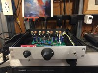
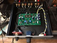
Here is my build:
Xmas Board w/ matched Toshiba JFETS (thank you Papa!)
DIY store Galaxy 1U 230X230 chassis
Glassware Audio "Select 2" 3-input switch
Alps 50K "Blue Velvet" audio taper pot
Kemet PS caps (1000ufd)
Elna Silmic II signal caps (10ufd)
Vishay CMF-series resistors
Mean Well PS w/ CUI jack
Military-style knobs (EHC and Grayhill)
REAN NYS367-series RCA jacks
Attachments
- Home
- Amplifiers
- Pass Labs
- B1 with Korg Triode