Reply to Manniraj
Sorry for the late reply, I have been caught up in many projects. Diagram is attached.
@avdesignguru
Excellent and clean build. I am almost done with mine but using Salas 1.3 PSU with a 0-23v trafo to power the buffer. How did you connect the Alphs pot to the buffer board along with the Select 2 switch? Fortunately I have the same switch but with DACT type 50K log pot from eBay. Let me know the connections if you can via a simple diagram.
thanks
Sorry for the late reply, I have been caught up in many projects. Diagram is attached.
Attachments
Hello,
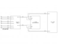
About the ground path,
why using single line path instead of ground plane?
Are there any reasons for this?
Thanks.
Ground planes are best reserved for digital circuits. Audio circuits do not generally benefit from a ground plane, as they may result in ground ‘loops’ which cause hum. The standoffs may be used to optionally make a connection with the chassis, but again this may not be preferable.
Sorry for the late reply, I have been caught up in many projects. Diagram is attached.
Thank you, so you are using the original Alps 50k pot right? So the wiring diagram from your pic is for the first row 3 pins and then followed by next row of 3 pins on the potentiometer.
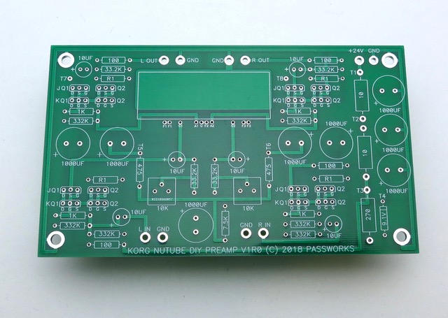
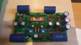
Finished mine yesterday. I had already built the Pete Millett one so instead of buying another nutube I removed it from Millett's board and installed it on this one. Was not that hard removing it but installing it on another board after bending the pins was another matter. Trying to get all those twisted pins to line up with the holes was not easy. The pins are small and easily misshaped. But all's well that ends well. I installed the board in the same case that the Millett board was installed in making the project easy. After a short listening I like the sound effect with my version of the F7 clone. Worthy project I am glad I built.
Ground planes are best reserved for digital circuits. Audio circuits do not generally benefit from a ground plane, as they may result in ground ‘loops’ which cause hum. The standoffs may be used to optionally make a connection with the chassis, but again this may not be preferable.
Ground planes are extremely useful for ANY switching signal! Every signal requires a return current. Not having a ground plane creates a ground loop within the PCB itself. Granted a poorly designed ground plane is sometimes worse than none at all but a properly designed PCB with a GND plane will outperform one without any day. If I designed PCBs without GND planes I would never pass emission and immunity testing and I've been doing this for 25 years! 😉
See this thread.
I have an elderly Antique Sound Lab autoformer volume control box that has been in and out of my system at various points, for various reasons - mostly convenience. Several inputs, multiple parallel outputs, and, important in my case, a known good working device for when I screw up other alternatives.
I've been looking for a way to incorporate the B1 Korg in my current system, and my first thought was to put it in the ASL box, but the board is just too big. The ASL does have, however, what is now a somewhat quaint feature: a switchable tape loop. May I assume that I could just put the B1 Korg board in an outboard box, with 50k resistors across the inputs, and have a convenient, versatile preamp with switchable gain and H2, along with, given the autoformers, the iron component that ZM suggests from time to time?
Answer: yes, or rather, YES!
sounds promising !! pictures of the result?
or am I jumping the gun and my assumption that YES is not an overwhelming exclamation of success
..dB
or am I jumping the gun and my assumption that YES is not an overwhelming exclamation of success
..dB
No pics yet, because I borrowed my LX Mini crossover chassis to house it, and I'm working up the courage to get my actual compact chassis drilled and screwed.
The sound is great, so much so that last night, instead of watching the NCAA tournament (without Marquette, who really cares, though) I listened to music the entire evening. I need to experiment with speaker phase and B1 voltage tweaking, but it immediately shocked me by producing sound sources that caused me to turn my head, looking at instruments seemingly at almost 90 degrees. Kind of like a Carver Sonic Holography machine, but one that actually works.
Thanks once again to Papa for the Xmas gift!
Christmas B1Korg
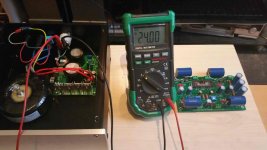
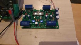
Finaly built and tested the christmas b1korg numbers are as follows
T1 24.00 vdc
T3 23.00vdc
T4 9.07 vdc
T5 0.6 vdc
T6 0.6 vdc
T7 9.49-9.51 vdc (after 10 minutes)
T8 9.49-9.51 vdc (after 10 minutes)
These numbers appear to fall within accepted limits. Have played no music yet as have to dissamble b1 to put b1 korg in .All info suggest that volume pot has to be 50k is it possible to use pots i have now ie 20k pots or a 100k pot that a have lying around this is an original arek kallas pot in silver plated cotacts when h e first bought them out some years ago. One other query is there anywhere on the board a led can be attache led indicate power on. Anyway thanks again to nelson for giving us this gift as well as to anybody that can help with the queries that i have hope to appreciate all it can do soon.Regards Spades
Attachments


20k pot will work beautifully.
Steal power for the LED somewhere from the PSU section, where isn't critical.
Steal power for the LED somewhere from the PSU section, where isn't critical.
Hi 6L6 thanks for the speedy reply for the led would that be where the power come into the board or off the power supply in the separate case that i use will i also need resistor for the led if so what value should i be using .Regard Spades.
answer to spades #1855
Hello SPADES,
steel the 24V from the power input of your pcb.
Resistor value depends on your LED you want to use.
My blue LEDs I most often use run between 20mA and 30mA.
(Check datasheet of your LEDs!)
U = 24V
I (Led) = 20mA - 30mA
U:I= R
24 V : 0,020A = 1.200 Ohm
24 V : 0,025A = 960 Ohm
24 V : 0,030A = 800 Ohm
Greets
Dirk
No reason why not. Just adjust the values of the input resistors to function as a
divider to take the gain down to something around unity.
divider to take the gain down to something around unity.
Thanks for the info cubicincher will try this out at the weekend hopefully and will then get the b1korg installed in its case and thus have a listen looking forward to hearing how it sounds.Regards Spades
You are in for a treat. My swap from B1 to Korg was mind-blowing. Though I had an annoying ticking sound in speaker an I thought that it was a bad joint ("spliff" in Swedish?) but in was not. It appeared when settled beside other electrical stuff. Now I'm going to install B1 Korg on the floor. I'm very pleased with my setup now but hopefully many problems is lurking around the corner. 10K pot on B1 korg paired with M2 gives me a big smile. 🙂[...] yet as have to dissamble b1 to put b1 korg in [...]
Myb1 korg will be mated to a pair of f2j whilst i wait for some parts for the f1j iam looking forward to it.Regards spades.
I didn't get any responses to my original post so thought I might try one more time. I have gone ahead and ordered another NuTube from the store - hopefully will be here tomorrow and I can swap the part out.
Does anybody have any other theories as to what I might check? All the other measurements from the FirstWatt article mentioned are within spec.
Also - what would be the best way to implement an LED to indicate power on/off?
Thank you for pointing me in the correct direction, H and B voltages measure 8.99
The replacement NuTube I ordered arrived. I carefully replaced it. Same result. Much frustration, rechecked measurements, checked another time for cold solder joints, remeasured everything and was writing down the measurements to start another post asking for help when I noticed that I had the input buffer 10uf capacitor installed with the incorrect polarity - switched it around and bingo - everything specs out great and problem solved.
I guess now I have an extra NuTube for 40 years from now the one installed needs replacement.
Now time to do some listening.
I guess now I have an extra NuTube for 40 years from now the one installed needs replacement.
Sounds like a great excuse.. I mean reason.. to build another for experimenting 😀
Good to hear you solved your issue and look forward to reading your impressions
You are in for a treat. My swap from B1 to Korg was mind-blowing. Though I had an annoying ticking sound in speaker an I thought that it was a bad joint ("spliff" in Swedish?) but in was not. It appeared when settled beside other electrical stuff. Now I'm going to install B1 Korg on the floor. I'm very pleased with my setup now but hopefully many problems is lurking around the corner. 10K pot on B1 korg paired with M2 gives me a big smile. 🙂
B1 Korg really does sound good. It is quite the 'mighty mite' as it turns out. Maybe half way between an indirectly heated small triode and a directly heated triode in sound quality. Open, non-compressing, and sweet. One would just not expect this to do so well, even with the impressive Pass imprimatur.
I tried mine with headphones again. Sony MDR Z7 @ 102db/mW and 70 ohms impedance. At this sensitivity, the huge 1.7 mW from the Korg and whatever buffer boost is within range of the headphones.
It sounded hypnotic, even though there is no polarity reversal with headphones to invoke the H2 negative state. I guess one could install some kind of chassis switch to reverse polarity at the output.
Nonetheless, I don't think it would serve as a general headphone device without the additional opamp boost as in Pete Millet's device.
- Home
- Amplifiers
- Pass Labs
- B1 with Korg Triode