OK I'm going over & over through the datasheet, and cannot find the 1.2V RMS and 3.5V p-p mentioned posts above by Richard. What I see is:
Can anyone help me understand how to get the VRMS and Zout? I suspect they would be 0.8333V from Vref and 833Ω from Ohm's law, respectively, but don't match any value mentioned in the thread.
Thank you so much
Code:
(at 5VDD)
Io(p-p) 1.0mA,
Vref 0.8333V,
Rref 11.4kΩ, and
Ibias of 1.08mA
Can anyone help me understand how to get the VRMS and Zout? I suspect they would be 0.8333V from Vref and 833Ω from Ohm's law, respectively, but don't match any value mentioned in the thread.
Thank you so much
See page 8 of the datasheet. Here, peak-to-peak voltage is 0 to 3.5v defined by "DC output voltage compliance".
Now, somebody needs to confirm I have the following correct, but: see here for a discussion on RMS, but the short version is: RMS = Vp/sqrt(2). I think we want to call Vp = 3.5/2 = 1.75 here, because it's not -3.5 to 3.5, but 0 to 3.5. 1.75/sqrt(2) is 1.2374.
Now, somebody needs to confirm I have the following correct, but: see here for a discussion on RMS, but the short version is: RMS = Vp/sqrt(2). I think we want to call Vp = 3.5/2 = 1.75 here, because it's not -3.5 to 3.5, but 0 to 3.5. 1.75/sqrt(2) is 1.2374.
See page 8 of the datasheet. Here, peak-to-peak voltage is 0 to 3.5v defined by "DC output voltage compliance".
Now, somebody needs to confirm I have the following correct, but: see here for a discussion on RMS, but the short version is: RMS = Vp/sqrt(2). I think we want to call Vp = 3.5/2 = 1.75 here, because it's not -3.5 to 3.5, but 0 to 3.5. 1.75/sqrt(2) is 1.2374.
THANK YOU! I think I finally understand it 🙂 Let's see, bear w/ me a little more 🙂
So, I guess Zout could be calculated as:
R = (Vpp/2)/I = 1.75V / 0.001A = 1k75Ω Zout
Does all this make any sense to you guys?
Its not making sense to me as you've taken the peak (rather than peak to peak) voltage but divided that by the peak to peak current. To get accurate answers you can't mix the ways of measuring the parameters of an equation.
Its not making sense to me as you've taken the peak (rather than peak to peak) voltage but divided that by the peak to peak current. To get accurate answers you can't mix the ways of measuring the parameters of an equation.
Sh*t, OK then I guess it must be
Zout = Vpp/Ipp = 3.5V / 0.001A = 3k5Ω Zout
Better now?


Here's a rough first draft of the filter
OK Abraxalito, I'm at this point now. A bit ashamed to admit I can not read that draft, since I don't see where the IN, OUT and GND are in that schematics. I modified the draft as I guess in/out/gnd are, I'd appreciate if anyone can confirm/correct.
Thank you
Attachments
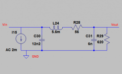
Yes that's correct - except (nit-picking point here) the 'Vin' is actually an Iin as the TDA1387's a current output DAC. The current source I15 represents the DAC.
Yes that's correct - except (nit-picking point here) the 'Vin' is actually an Iin as the TDA1387's a current output DAC. The current source I15 represents the DAC.
Wow, great! Oh yes, obviously Iin.
I just chcked your lingdac iv bom and see many pnp and npn. I thought you would also use passive iv.
I gave up on passive I/V a while back - active sounds so much better, particularly in the bass, provided a passive filter is used before the active stage.
I gave up on passive I/V a while back - active sounds so much better, particularly in the bass, provided a passive filter is used before the active stage.
ok one more stupid question, bear with me.
I understand passive I/V purpose is HF rolloff to avoid next opamp/s oscillation. What is the purpose of the active stage afer the passive? Maybe reducing impedance? Add capacitance? Add some gain? ...?
Thank you again for your patience
I don't think the purpose of passive I/V is to prevent oscillation. Rather it allows the transformation from I to V to happen with negligible intermodulation distortion.
When you ask of the purpose of the active stage after passive are you asking in the context of my lingDAC design or in the context of more traditional passive I/V followed by a post-amplifier?
When you ask of the purpose of the active stage after passive are you asking in the context of my lingDAC design or in the context of more traditional passive I/V followed by a post-amplifier?
I don't think the purpose of passive I/V is to prevent oscillation. Rather it allows the transformation from I to V to happen with negligible intermodulation distortion.
When you ask of the purpose of the active stage after passive are you asking in the context of my lingDAC design or in the context of more traditional passive I/V followed by a post-amplifier?
Ok. Just trying to understand the general use, yes. I’m planning to use a passive I/V followed by a LME49720 with gain, a digital pot and finally a driver to convert to differential. Since you say you’re now also using an active stage after the passive, I was curious on the why’s and also what was the main function of the active stage. Thank you again
The main function of the active stage in lingDAC is to present a low impedance to the current source output of the DAC, one considerably lower than would normally be achieved when using passive I/V. From memory its in the region of 50ohm or so.
The main function of the active stage in lingDAC is to present a low impedance to the current source output of the DAC, one considerably lower than would normally be achieved when using passive I/V. From memory its in the region of 50ohm or so.
super awesome, thank you again
Hey abraxalito,
When you design low pass filter, what's the desired cutoff HF? 20kHz? Or since that's a curve going down we can do with half of that?
TY
When you design low pass filter, what's the desired cutoff HF? 20kHz? Or since that's a curve going down we can do with half of that?
TY
Also, I've seen HF rollof filters made of RC and other made of RL. Yours use LRC. Is there a rule to choose between them?
As usual, the answer depends... If the filter's highly constrained (like I can't use more than 2 inductors for cost or space reasons) then I'll go for a lower cutoff freq to get more stopband rejection. But for cost-no-object designs the nearer to 20kHz cutoff the better. Bear in mind that FM radio has an upper bandwidth limit of 15kHz and I don't recall hearing people saying that's lacking top-end.
As regards RC and RL - presumably the RC are used in conjunction with opamps to provide positive feedback? I haven't seen RL used as C is much more manageable than L - better tolerances, lower losses, better temperature stability, smaller, cheaper. A passive filter which doesn't use both L and C is going to be severely limited in how steep a roll-off it can achieve.
As regards RC and RL - presumably the RC are used in conjunction with opamps to provide positive feedback? I haven't seen RL used as C is much more manageable than L - better tolerances, lower losses, better temperature stability, smaller, cheaper. A passive filter which doesn't use both L and C is going to be severely limited in how steep a roll-off it can achieve.
As usual, the answer depends... If the filter's highly constrained (like I can't use more than 2 inductors for cost or space reasons) then I'll go for a lower cutoff freq to get more stopband rejection. But for cost-no-object designs the nearer to 20kHz cutoff the better. Bear in mind that FM radio has an upper bandwidth limit of 15kHz and I don't recall hearing people saying that's lacking top-end.
Good then, I'll use 20K directly. The question was because I think that Fc is the first -3dB cut, but the curve still goes down from there so the final cutoff is a bit higher HF. (If that makes any sense, I'm the newbie here)
As regards RC and RL - presumably the RC are used in conjunction with opamps to provide positive feedback? I haven't seen RL used as C is much more manageable than L - better tolerances, lower losses, better temperature stability, smaller, cheaper. A passive filter which doesn't use both L and C is going to be severely limited in how steep a roll-off it can achieve.
No idea, tbh. But I saw RC or RL w/o opamps in this calculator, that's why I asked here to the expert 😀 Maybe you can recommend a better calculator?
Thank you again
Last edited:
- Home
- Source & Line
- Digital Line Level
- tda1387 dac pcb "front end"