I am running 32bit Win XP. Akabak runs fine, it's the copy and paste between the virtual machine firewall that doesn't work.
I am running 32bit Win XP. Akabak runs fine, it's the copy and paste between the virtual machine firewall that doesn't work.
Does copy and paste work inside your WinXP?
I was just thinking that by installing Win7, the problem might go away.
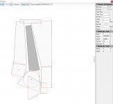
I tried my best to model a 0.4x TC9FD karlsonator in the, now defunct, Transmission Line beta program by leonard audio. I realize that the experts herein use akabak, but I couldn't get to run on my PC. I haven't tried a VM of Winxp yet though.
All that said, I don't really know what I am doing, but I set it up as a tapped horn design and did my absolute best to match up the "areas" to the dimensions in the score-n-fold plans. Is this a suitable method of modeling a design such as this? Or am I fundamentally missing the point and oversimplifying the physics?
I have enclosed a zip of my file. Please edit it, criticize, suggest alternative methods, etc to your hearts' content! I'd rather be disappointed but correct than happy and wrong.
Attachments
I realize that the experts herein use akabak, but I couldn't get to run on my PC. I haven't tried a VM of Winxp yet though.
Akabak also works in 32-bit Windows 7, should you wish to try it.
I tried my best to model a 0.4x TC9FD karlsonator in the, now defunct, Transmission Line beta program by leonard audio. I realize that the experts herein use akabak, but I couldn't get to run on my PC. I haven't tried a VM of Winxp yet though.
All that said, I don't really know what I am doing, but I set it up as a tapped horn design and did my absolute best to match up the "areas" to the dimensions in the score-n-fold plans. Is this a suitable method of modeling a design such as this? Or am I fundamentally missing the point and oversimplifying the physics?
I have enclosed a zip of my file. Please edit it, criticize, suggest alternative methods, etc to your hearts' content! I'd rather be disappointed but correct than happy and wrong.
I don't have Leonard Audio TL program so can't look at what you have done, but you can indeed model a lot of it if you follow the dimensions ad make a tapped horn. The main difference is that the effect of the Karlson aperture probably is not modeled well in the LATL program.
More details of how the K aperture is modeled in Akabak is shown here:
Karlson
This is for the K15, but same principles apply to Karlsonator aperture, and the back chamber is a TQWT-MLTL...
You will know that the model sort of approximates a Karlson when you get the characteristic Karlson "W" dips in the 200Hz to 400Hz range. No one ever said the Karlson is a flat response speaker, but narrow dips are hard to hear, but it makes up for it with a wide soundstage and smooth wide polars and excellent dynamics.
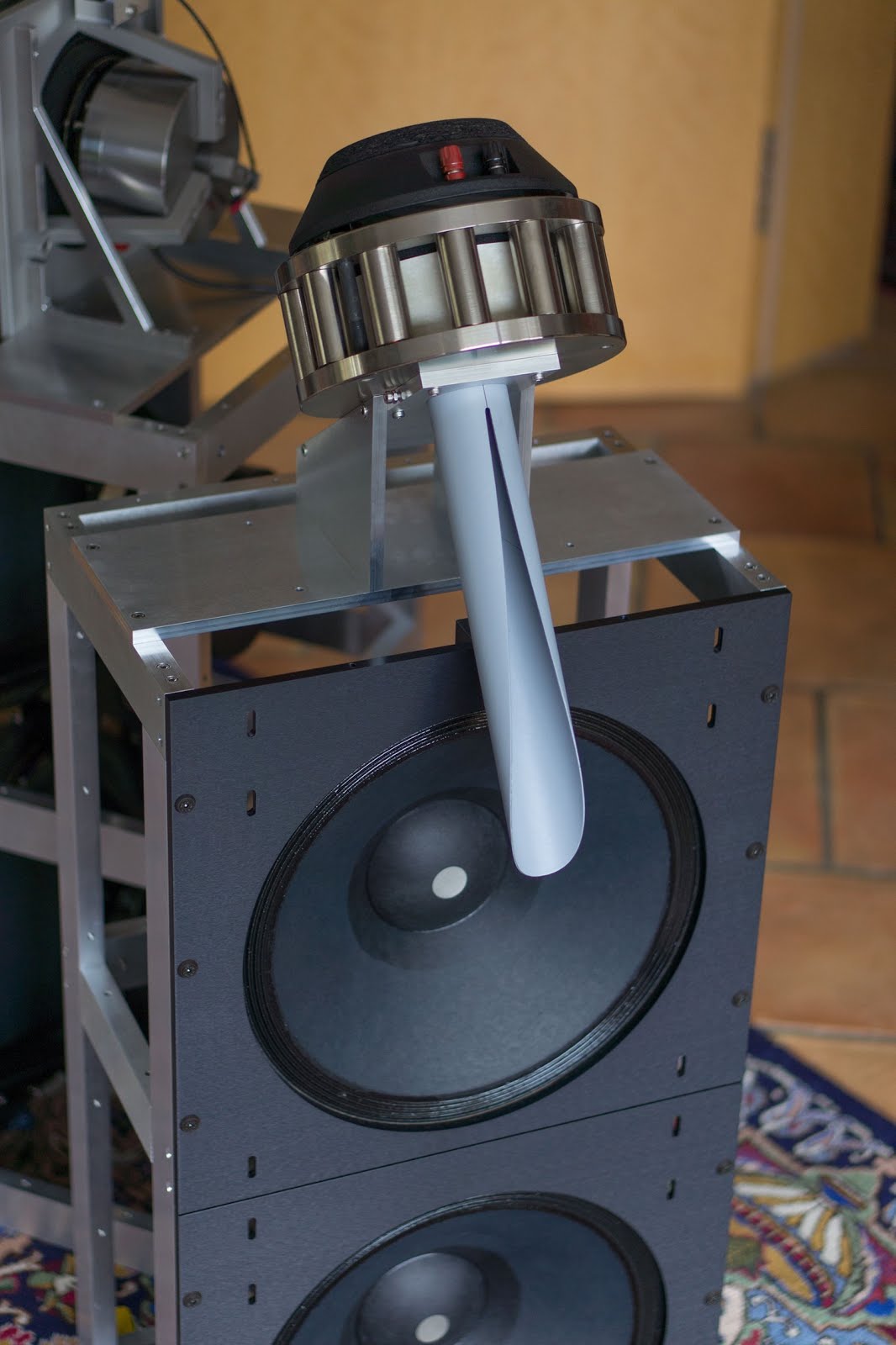
First test, so far so good.
Will add some paint and finish the damping eventually..
They turned out a lot bigger than expected 🙂


Will add some paint and finish the damping eventually..
They turned out a lot bigger than expected 🙂
Last edited:
You will know that the model sort of approximates a Karlson when you get the characteristic Karlson "W" dips in the 200Hz to 400Hz range. No one ever said the Karlson is a flat response speaker, but narrow dips are hard to hear, but it makes up for it with a wide soundstage and smooth wide polars and excellent dynamics.
It doesn't look exactly like a "W" but I think it might be what you are describing? You are right that simulating the aperture in TLbeta is impossible (I think). Is the "W" a result of the aperture or the design of the enclosure? If the former, then I imagine I am incorrect.
Thanks so much for the help! This community is the best
Attachments

First test, so far so good.
Will add some paint and finish the damping eventually..
They turned out a lot bigger than expected 🙂
View attachment 725075View attachment 725076
As I remember, the tubes work best if they are inside the cabs with the mouth poking out of the top of the woof horn slot. Looking good by the way.
Yes I'm going to experiment with the whole Tweeter setup and damping. The project started because I had some ~10$ speakers laying around. Now 150$ cabinets later can't say I regret it, I am very impressed with the amount of depth I get from this speakers.As I remember, the tubes work best if they are inside the cabs with the mouth poking out of the top of the woof horn slot. Looking good by the way.
First test, so far so good.
Will add some paint and finish the damping eventually..
They turned out a lot bigger than expected 🙂
View attachment 725075View attachment 725076
Nice work! What drivers are those again?
It doesn't look exactly like a "W" but I think it might be what you are describing? You are right that simulating the aperture in TLbeta is impossible (I think). Is the "W" a result of the aperture or the design of the enclosure? If the former, then I imagine I am incorrect.
Thanks so much for the help! This community is the best
You may have it there - but the “W” is not quite as pronounced and rather higher up in frequency range.
Here is closer to a W that I am talking about.
First test, so far so good.
Will add some paint and finish the damping eventually..
They turned out a lot bigger than expected 🙂
View attachment 725075View attachment 725076
I like those! That's a cool form factor for sure!
love those tall K's 😀
here's my old tall K18's in room response (sitting away from walls)
18" woofer only - no lowpass. Mounting the K-tube in the front
chamber works very well vs on top.

here's my old tall K18's in room response (sitting away from walls)
18" woofer only - no lowpass. Mounting the K-tube in the front
chamber works very well vs on top.
love those tall K's 😀
here's my old tall K18's in room response (sitting away from walls)
18" woofer only - no lowpass. Mounting the K-tube in the front
chamber works very well vs on top.
3d printed some new ones and the combination sounds great. Waiting for some measurement equipment and will send you the response of this setup when I get it.

K-enthusist Carl Neuser made some of his K-tubes (including oval per Karlson's Open End Waveguide patent) from laminated wood veneer. One of the original K-15 tubes was 1.875" diameter and used a 1" driver with oddball looking transition. That adbrupt diameter transition made a rough looking response (in reality it sounded good) 1 inch compression drivers are very suitable for K-tube duty. Another X15 Karlson speaker had a tube which looked to be ~1.3" diameter. The Transylvania Power Company product "The Tube" was very well made, relatively free from ringing, and started with 1" entrance with sidewalls tapering downwards ~2 degrees.
The graph traces below are for a homemade 1" pvc tube vs a longer version of one X15 tube with 1.875" ID. There was a 1.5" pre-waveguide - scattering device in the big tube - just 1"Id tubing sliced at ~30 degrees. Subjectively that big tube sounds much like a very good FR speaker in tonal quality.
Also, the short stub extension on my homemade thinwall pvc K-tube created a notch below 2K. An extension is handy when mounting a K-tube in a Klam or Karlson front chamber to get enough length to reach the compression driver behind the panel and to have the K-tube's exit near the main
K-aperture plane.
HF's go pretty much straight down a K-tube. The rolloff above 12K in the test below was from Eminence's aluminum diaphragm "type 1" compression
driver. Later, Eminence shifted production to titanium which went "higher".

Laminated paper should be pretty good for a K-tube. I'm not sure what Wolf von Langa used for his K-tubes. (its kinda a shame he adbandoned K-tech - I think that decision was based on aesthetics vs the market - a tube could be hidden behind grill cloth or screen)
Because there's little or no LF gain from a typical K-tube plus some narrowing in directivity on the high end, a compression driver needs no frequency contouring at all - just the highpass network. It will still keep up with 100-102dB systems.
Like a small and unbaffled horn, I think some K-tube setups would benefit from a baffle located at the driver's exit plane.

A mini K-lens with shallow chamber depth over a paper cone (CTS "phenolic ring" knockoff tweeter altered its horizontal polars to look pretty wide

120 degree horizontal dispersion at HF from that phenolic ring tweeter is really pretty good

With car coax and central/concentric dome tweeter - a K-tube can be cemented to the dome's baffle. with a "klam" that
will remove a lot of the HF's inteaction with the chamber reflections
The graph traces below are for a homemade 1" pvc tube vs a longer version of one X15 tube with 1.875" ID. There was a 1.5" pre-waveguide - scattering device in the big tube - just 1"Id tubing sliced at ~30 degrees. Subjectively that big tube sounds much like a very good FR speaker in tonal quality.
Also, the short stub extension on my homemade thinwall pvc K-tube created a notch below 2K. An extension is handy when mounting a K-tube in a Klam or Karlson front chamber to get enough length to reach the compression driver behind the panel and to have the K-tube's exit near the main
K-aperture plane.
HF's go pretty much straight down a K-tube. The rolloff above 12K in the test below was from Eminence's aluminum diaphragm "type 1" compression
driver. Later, Eminence shifted production to titanium which went "higher".
Laminated paper should be pretty good for a K-tube. I'm not sure what Wolf von Langa used for his K-tubes. (its kinda a shame he adbandoned K-tech - I think that decision was based on aesthetics vs the market - a tube could be hidden behind grill cloth or screen)
Because there's little or no LF gain from a typical K-tube plus some narrowing in directivity on the high end, a compression driver needs no frequency contouring at all - just the highpass network. It will still keep up with 100-102dB systems.
Like a small and unbaffled horn, I think some K-tube setups would benefit from a baffle located at the driver's exit plane.
A mini K-lens with shallow chamber depth over a paper cone (CTS "phenolic ring" knockoff tweeter altered its horizontal polars to look pretty wide
120 degree horizontal dispersion at HF from that phenolic ring tweeter is really pretty good
With car coax and central/concentric dome tweeter - a K-tube can be cemented to the dome's baffle. with a "klam" that
will remove a lot of the HF's inteaction with the chamber reflections
Last edited:
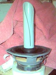
Once again just something cheap I had laying around.What drivers are you using in the tubes? I'd love to try a set.
13DT48P - Hifi - Hogtalarelement - Komponenter
They are a little harsh on their own but with the tube it behaves a lot smoother.
hey X - if you get time, would you come up with a well balanced Karlsonator for Moray James' Klipsch 10" speaker? All I have for the specs are: (maybe Moray has another set? -will find out in the next day)
I was somewhat ill for 6 weeks with flu symptoms - doing a bit better now
REVC 5.77 OHMS - DC resistance
FMS 35.7462
QES .4062
QTS .3546
Le 1.4056 mh
VAS 78.1875 L - 2.76116 ft^3
BL 12.0648
Sensitivity 91.1884 db 1w/1m
I was somewhat ill for 6 weeks with flu symptoms - doing a bit better now
REVC 5.77 OHMS - DC resistance
FMS 35.7462
QES .4062
QTS .3546
Le 1.4056 mh
VAS 78.1875 L - 2.76116 ft^3
BL 12.0648
Sensitivity 91.1884 db 1w/1m
- Home
- Loudspeakers
- Full Range
- Mini Karlsonator (0.53X) with Dual TC9FDs