Thanx a lot Mooly!
I shall make my next component shopping according to your guidelines.
First prototype channel though now playing without any explosions 🙂
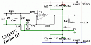
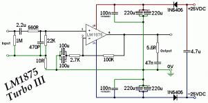
Regarding the 220R VR potentiometer at the input, I wonder what function this component has?
Regards Kurt
I shall make my next component shopping according to your guidelines.
First prototype channel though now playing without any explosions 🙂
Regarding the 220R VR potentiometer at the input, I wonder what function this component has?
Regards Kurt
You're welcome 🙂 and pleased to hear you have one channel working.
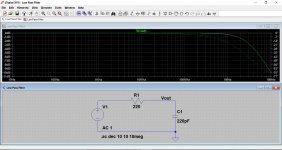
The 220 ohm... only Daniel can explain that one 😀
What it does do is interact with the 220pF cap to form a low pass filter although imo the effect of it is minimal with those values. If you turn the pot to a low value resistance, or even to zero ohms, then the 220pF cap effectively appears in parallel to whatever you connect to the input and in certain cases that might cause problems rather than help matters.
I would recommend fitting something like a fixed 1k resistor in place of the preset.
You mean leaving the 220p cap and just replacing the 200R pot with a 1k resistor?
I trust that Daniel will enlighten us at some time.
I also asked him about the sound quality of the original schematic vs the Turbo II.
Do you know about the differences between the 2?
I trust that Daniel will enlighten us at some time.
I also asked him about the sound quality of the original schematic vs the Turbo II.
Do you know about the differences between the 2?
I've no idea on sound quality at all I'm afraid as I've never even built a chip amp for serious listening.
The 1k and 220pF form a filter with a -3db point of over 700kHz and so any effect it has will be marginal. Its Daniels choice of how he wanted to do it though.
The 1k and 220pF form a filter with a -3db point of over 700kHz and so any effect it has will be marginal. Its Daniels choice of how he wanted to do it though.
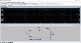
I should have said that Daniels 220 ohm and 220pF form a filter with a -3db point of over 3MHz, and even higher if you turn the pot down.
Now I better understand, why I couldn’t hear any difference no matter the position of the potentiometer 🙂
My testspeakers are not the best but still.
With your explanation of the function of the cap and resistor I wonder why he put a potentiometer there instead of a fixed resistor.
My testspeakers are not the best but still.
With your explanation of the function of the cap and resistor I wonder why he put a potentiometer there instead of a fixed resistor.
You would have to ask Daniel that one 🙂
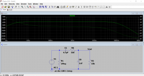
This shows graphically how the filter shapes the response. Look at the scale at the left. The second example would be more typical of values used in other designs.
One of the main functions of such a filter is to keep out interference.
This shows graphically how the filter shapes the response. Look at the scale at the left. The second example would be more typical of values used in other designs.
One of the main functions of such a filter is to keep out interference.
Attachments
Dear Gurus, I would be using 18v-0-18v 3A transformer; I would like to use fuses on the power supply module as well as on the amplifier modules. How much amperage should the fuses be rated at? Should they be the same? Also should I use slow-blo or fast-blo versions?
Thank you.
Thank you.
At least I am first with a suggestion:
1A "slow-blo" for the transformer primary and 5A or 6A "slow-blo" for the amplifier board.
1A "slow-blo" for the transformer primary and 5A or 6A "slow-blo" for the amplifier board.
I'm in the process of building an LM1875 amplifier.
I have a question regarding the low pass RC network in the input of the amplifier: Does it make any difference if the RC network is put before or after the input DC blocking capacitor?
I have a question regarding the low pass RC network in the input of the amplifier: Does it make any difference if the RC network is put before or after the input DC blocking capacitor?
It shouldn't make any difference where you place it but its always best to draw exactly what you mean and and include the complete network, then we can be 100% sure in our advice.
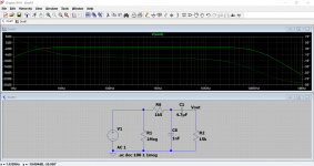
Referring to the schematic below, borrowed from post #693:
Should the R6/C8 network be in front or behind C1?

Should the R6/C8 network be in front or behind C1?
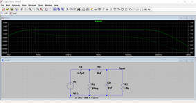
Common mode relates to a signal effectively appearing in series with both inputs.
For minimum common mode gain (maximum rejection of common mode signals) both inputs need to see the same impedances over the range of frequencies involved. That means the 2.2uF, 470pF and 100uF's would have to go (DC coupled) and the 22k would need to be made equal to the 100k. You would also need a 2k7 in series with the input. The 560 ohm would need to be linked out.
So that just isn't practicable for that configuration.
Can anyone please guide me which PCB to buy for gainclone?
I am after most refined PCB which has ideal layout/component selection as per geeks here.
Many Thanks in advance
I am after most refined PCB which has ideal layout/component selection as per geeks here.
Many Thanks in advance
It does exist!Can anyone please guide me which PCB to buy for gainclone? I am after most refined PCB which has ideal layout/component selection as per geeks here.
LM3886 Done Right
But, it doesn't use LM1875.
I had meant to get close, perhaps just for sport. In this case, I wanted the dividers at + and - to be same voltage proportions. The question is, did I get the input RF filter done right?Common mode relates to a signal effectively appearing in series with both inputs. For minimum common mode gain (maximum rejection of common mode signals) both inputs need to see the same impedances over the range of frequencies involved. That means the 2.2uF, 470pF and 100uF's would have to go (DC coupled) and the 22k would need to be made equal to the 100k. You would also need a 2k7 in series with the input. The 560 ohm would need to be linked out. So that just isn't practicable for that configuration.
Attachments
Last edited:
- Home
- Amplifiers
- Chip Amps
- Beginner's Gainclone, HiFi LM1875, The Amplifier Board