Un-encaspsulating one of these critters would have been my first order of business if i were into LDRs. And obviously experimenting with alternative light sources, slower and less capable of transmitting PS noise.
No idea why a TL431 datasheet is attached or in what way it disagrees with my opinion.
"Opto-Coupler Linearisers "
Because a battery vs a 5v linear wall wart supply, each fail to distance the anode and cathode of the internal LED anode and cathode from the DC supply sufficiently. Try distancing the anode firstly then the the cathode as well, from any capacitance resistance or supply parallels.
I guess I should have studied alchemy. Then I might understand why 'distancing' the two terminals of a light source might affect the light it emits.
Let's humour Chris for a moment. If he is right about current drive being necessary then it is only necessary to have a high impedance at one LED connection, not both. This is because the LED is not actually connected to the LDR; it merely shines light on it. That is why optocouplers are sometimes opto-isolaters.
Let's humour Chris for a moment. If he is right about current drive being necessary then it is only necessary to have a high impedance at one LED connection, not both. This is because the LED is not actually connected to the LDR; it merely shines light on it. That is why optocouplers are sometimes opto-isolaters.
Btw, the well liked DHT heating supplies which Rod Coleman sells are based on a similar concept: both sides of the filament are isolated. Perhaps valve guys are just cool with weirdness and simply like the way the regulators sound.
As for "Opto-Coupler Linearisers" i have a suspicion it is the transfer function from input to output that gets linearised, not the resistance of the LDR. Feel free to prove me wrong.
As for "Opto-Coupler Linearisers" i have a suspicion it is the transfer function from input to output that gets linearised, not the resistance of the LDR. Feel free to prove me wrong.
I guess I should have studied alchemy. Then I might understand why 'distancing' the two terminals of a light source might affect the light it emits.
Let's humour Chris for a moment. If he is right about current drive being necessary then it is only necessary to have a high impedance at one LED connection, not both. This is because the LED is not actually connected to the LDR; it merely shines light on it. That is why optocouplers are sometimes opto-isolaters.
High impedance works well with just the anode, though is better at each end because it distances the cathode as well then from any interaction with signal ground potential, or grounding variance from ideal detailed here.
Staying Well Grounded | Analog Devices
I thought you weren't connecting it to signal ground, you can't get much farther away than that.
I thought you weren't connecting it to signal ground, you can't get much farther away than that.
Correct, however sensible option is provided with back to back schottky or UF type diodes, seen in the Analog Devices document at Grounding summary, for what happens in real circumstances namely the unplugging or plugging of RCA's in consumer audio equipment.
I notice no audio change one to the other, but if there is no possibility of unplugging or plugging, indeed the back to back diodes need not be used, making DC ground and signal ground entirely isolated.
It is perhaps my fussiness with achieving everything possible from a NSL32SR3 that led me to find small differences by having high impedance gap necessary also with the cathodes. This is mainly because of the location of the single gang potentiometer for volume adjustment which is placed below the cathodes, the wiper being 8.6v below the cathodes at normal listening levels, and the wiper then 0.593v from DC ground.
Last edited:
OT, but
Would this have relevance in cathode bypass application?
I’ve suppose this has been dug up in one of those threads.
Generally speaking I just can’t seem to shake my hatred for the light quality they give off. Love a good halogen.... pity they’re not more environmentally friendly.
Not a comparable situation: a DHT filament is highly connected to the circuit; an optocoupler LED is not.analog_sa said:Btw, the well liked DHT heating supplies which Rod Coleman sells are based on a similar concept: both sides of the filament are isolated.
Repeating somethng which is untrue does not make it become true. Surely your LED driver is separate from the signal circuit, anyway?Chris Daly said:High impedance works well with just the anode, though is better at each end because it distances the cathode as well then from any interaction with signal ground potential, or grounding variance from ideal detailed here.
You have measurements?It is perhaps my fussiness with achieving everything possible from a NSL32SR3 that led me to find small differences by having high impedance gap necessary also with the cathodes.
Not a comparable situation: a DHT filament is highly connected to the circuit; an optocoupler LED is not.
I tried to point out the Opto LED is not
Repeating somethng which is untrue does not make it become true. Surely your LED driver is separate from the signal circuit, anyway?
Also asked and answered. I guess if you keep the BS going it will become fact after a while.
You have measurements?
Also asked and answered and was refered to engineering data for the optocoupler. I offered to test and the offer was declined. So far the only thing going for Chris is his buddies glowing sonic comments. Haven't found anything in any amercian hi fi magazines only a ossi Diy forum. Kind of a slanted view.
Not a comparable situation: a DHT filament is highly connected to the circuit; an optocoupler LED is not.
Repeating somethng which is untrue does not make it become true. Surely your LED driver is separate from the signal circuit, anyway?
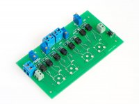
I think this has been explained quite a few times already, sorry you seem to have strangely missed those posts, See the attached image and refer back to prior posts that clearly show LED driver separated from signal ground, As explained in those posts end users of audio equipment may or may not plug and unplug audio leads, hence you will notice back to back diodes placed at the board edge, as advocated by Analog Devices see Grounding summary Staying Well Grounded | Analog Devices The use of schottky or UF type diodes is optional where end users are confident of not connecting or disconnecting RCA's , in which case they leave that wiring unconnected achieving isolation where RCA sockets are similarly insulated from chassis ground.
Are you offering ?You have measurements?
Attachments
Last edited:
I don't see a need for back to back diodes. The signal isn't connected to a digital device. This is just another case where parts are thrown in where they aren't needed. Unplugging or plugging in the RCA jacks in my opinion is going to have no effect. The signal is being connected or disconnected to either the input or output or both of the voltage divider.
Another point..... any knowledgeable person doesn't make connections to an amplifier when it is powered on. Doing so can and usually does result in amplifier or speaker damage or both. This includes the thumb test on the amplifiers RCA or XLR input cable.
Another point..... any knowledgeable person doesn't make connections to an amplifier when it is powered on. Doing so can and usually does result in amplifier or speaker damage or both. This includes the thumb test on the amplifiers RCA or XLR input cable.
Last edited:
The very first MkI's I made in the 70's with the Nikon lightmeter photocells, I used a 3 or 4" tube the same size as the photocells one was glued in each end, and a hole was drilled in the middle of the tube, for at the time all I had laying around were small neon bulbs for the lights source, similar to these. http://www.giangrandi.ch/electronics/neon/glowing-lamp-dc-neg-s.jpg
And to analog_sa above it is virtually impossible to detect the difference with regulated 5v with linear wall wart supply or a pure battery source, it is well documented.
The only time a difference was detected and measured, was when they were powered with SMP not linear wall warts, which raised the noise floor from a few uV's, this noise came in via the ground plane and some "think" they heard the difference.
Cheers George
Wasn't there an article published? I seem to remember reading something a long time ago.
When plugging in, problems can arise if the signal is connected before the ground. Some RCA plugs have spring loaded ground connections so this can't happen, usually it's reckoned though that any unplugging/plugging is done with the equipment off.
The presence (or not) of ground-breaker diodes does not change the fact that the current through an LED depends on the series connection of the items in the circuit loop containing the LED. If you have a CCS connected to one terminal then there is no need for a CCS (or anything else) connected to the other terminal - anything which will complete the loop will do; indeed if you have two CCS (which some of your remarks seem to imply) then they will fight each other for control of the current.Chris Daly said:I think this has been explained quite a few times already, sorry you seem to have strangely missed those posts, See the attached image and refer back to prior posts that clearly show LED driver separated from signal ground, As explained in those posts end users of audio equipment may or may not plug and unplug audio leads, hence you will notice back to back diodes placed at the board edge, as advocated by Analog Devices see Grounding summary Staying Well Grounded | Analog Devices The use of schottky or UF type diodes is optional where end users are confident of not connecting or disconnecting RCA's , in which case they leave that wiring unconnected achieving isolation where RCA sockets are similarly insulated from chassis ground.
However, it is conceivable that when you say 'current source' you merely mean a DC supply of indeterminate impedance, similarly for current sink. In that case you get the sum of the impedances. There is still no need to isolate one LED wire from ground.
No. You are the one making claims which differ from standard electronics understanding.Are you offering ?
Let us just assume for the moment that you found that apparently the distortion from the volume control was improved by changing the LED drive, including 'isolating' both LED wires, and you have measurements and double-blind listening tests to back this up. At that point you should start looking for mistakes in your circuit or measurements or listening test procedure, because the result you think you have found is impossible. As it is impossible then it can't be happening, so you should search to find out why you think it is happening. That is what I do when I get an impossible result.
Yes, I fully understand that plugging in a RCA depending on the type of RCA can result in the signal making contact before the ground. Any knowledgeable person simply doesn't do this. Still, the diodes are a waste of parts and board space. AS I pointed out the diodes are a necessity with digital circuitry but not simple analog.
Cost versus reliability.....
What we know about LED optocoupler volume controls.
1.) They aren't cheap in cost
2.) They have a limited life/hours
Resistive controls
1.) Contain a wiper which could result in limited contact. Note* Many can be purchased that are sealed and will last for many years.
2.) Can be composed of individual resistors to allow a number of DB steps.
The cost of LED couplers verses their cost is a matter that needs to be considered since the life of LED optocouplers can be down to 1,000 hours and they will need to be changed/replaced.
Sonic differences... LED controls don't track accurately and need to have matched elements which still don't track with each other. This may be one of the reasons people believe the sound stage is better.
No proof as to the LED units being any better other than word of mouth.
Wasn't there an article published? I seem to remember reading something a long time ago.
Yes, back then it was publish as something like the "non mechanical pot" in "Silicon Chip" and or "Electronics Australia" and was first reviewed in a hifi mag in the Australian "HiFi Review" by Richard Timmins (rip) and also by Doug Saunders (rip) who's system was something, in a converted old sandstone church, stacked quad 57's with Kelly Decca ribbon from 12khz up and from 100hz down to 2 x massive 100kg passive RTR subwoofers as coffee tables on each side of the listening lounge, all passive xovers, driven by a massive two man lift amp I made which was 150w pure Class-A water cooled (cooling jacket, small radiator, quite pump, slow rotating cooling fan)
The amp was loosely based on Nelson Pass's A20, highly expanded from 20w to 150w though, with local not global feedback. 36 x Hirel ED/EB 203/204 bi-polars, (beautiful transistor) 5kva tranformers and 3/4 of a farad of supply caps.
http://www.firstwatt.com/pdf/art_classa_20.pdf
Cheers George
Last edited:
Cost versus reliability.....
What we know about LED optocoupler volume controls.
1.) They aren't cheap in cost
2.) They have a limited life/hours
Resistive controls
1.) Contain a wiper which could result in limited contact. Note* Many can be purchased that are sealed and will last for many years.
2.) Can be composed of individual resistors to allow a number of DB steps.
The cost of LED couplers verses their cost is a matter that needs to be considered since the life of LED optocouplers can be down to 1,000 hours and they will need to be changed/replaced.
Sonic differences... LED controls don't track accurately and need to have matched elements which still don't track with each other. This may be one of the reasons people believe the sound stage is better.
No proof as to the LED units being any better other than word of mouth.
I am sorry to say but what you write is FUD,
Fear, uncertainty and doubt - Wikipedia
"a disinformation strategy used in sales, marketing, public relations, politics, cults, and propaganda. FUD is generally a strategy to influence perception by disseminating negative and dubious or false information and a manifestation of the appeal to fear"
I stand by my product and as my existing customers already know my customer service and commitment to their satisfaction is beyond reproach.
If in the extremely rare case there is any failure of an LDR board, it is replaced without charge and postage paid each way by myself to send and retrieve a board for testing. Such an event is extremely unlikely due to the low current used in my kits averaging 2ma and a maximum of 11ma
I suggest you improve your own audio system with the 3 input kit, you will
enjoy putting it together as well as adding to your appreciation of music.
- Status
- Not open for further replies.
- Home
- Source & Line
- Analog Line Level
- Chris Daley's Stereo Coffee Preamp