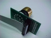
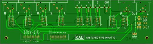
IO Switch Assembly Details in PICs
The Lorlin switch is adjustable as to the number of selector stops by simply moving the washer under the nut that has a 'finger' reaching into the switch body. That finger becomes a physical stop for the switch.
Sorry about your frustration. The attached PICs should clarify your assembly issues.
The Lorlin switch is adjustable as to the number of selector stops by simply moving the washer under the nut that has a 'finger' reaching into the switch body. That finger becomes a physical stop for the switch.
Sorry about your frustration. The attached PICs should clarify your assembly issues.
Attachments

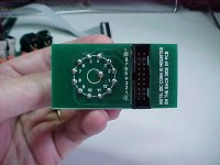
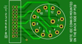
I fixed some issues with IDC not lining up with pin 1. So far I have inputs 3 and 5 working. I have not tried XLR's yet. Still don't understand switching yet. The position on switch are farther apart than expect to see. Too many switch positions between 3 and 5. Your board for switch is a different version than mine. A little bit confusing. to get pin one on IDC and the board pin 1 you have to put switch on side that says to put it on the opposite side. Do you have any more switch boards. May have messed something up on the board from solder -desolder. frustrated and calling it a nite.
... Do you have any more switch boards. May have messed something up on the board from solder -desolder. frustrated and calling it a nite.
Sure, we can fix you up. Please send me a private message and we will get your problems sorted.
Great thread
I really enjoyed reading through this thread. What a fantastic project.
Some of the cases were amazing. I thought the wood versions were quite special.
Cheers!
Peter
I really enjoyed reading through this thread. What a fantastic project.
Some of the cases were amazing. I thought the wood versions were quite special.
Cheers!
Peter
I/O board schematic
Carl, if its OK with you I can share my schematic of I/O board which is an exact replica? pdf file.
Best Regards
Farooq
Carl, if its OK with you I can share my schematic of I/O board which is an exact replica? pdf file.
Best Regards
Farooq
Carl, if its OK with you I can share my schematic of I/O board which is an exact replica? pdf file.
Best Regards
Farooq
Sure,
Please post it.
Anyone using a potentiometer with a center detent for balance and tone controls? Does this one look like a possible match?
5k ohm Dual Linear Rotary Potentiometer with Center Detent


5k ohm Dual Linear Rotary Potentiometer with Center Detent
Anyone using a potentiometer with a center detent for balance and tone controls? Does this one look like a possible match?
That looks to be a great choice!
Anyone using a potentiometer with a center detent for balance and tone controls? Does this one look like a possible match?
5k ohm Dual Linear Rotary Potentiometer with Center Detent
Great source for many pots! Thanks for the link!
Rotary Potentiometers
I'm in the process of ordering parts from mouser. I've doubled up on many of the parts on the top part for each channel. but the bottom section of the BOM_v13_01 is a bit confusing.
It says to get the following:
20 Pin IDC 2 Row Header 2 20 (10 x 2) HDR Vertical Double 20P Low Profile
20 Pin IDC 2 Row Cable 1 Ribbon Cable Flat Ribbon Cable - length varies
I think inking I need more than 2 row headers and more than 1 ribbon cable. I'm gathering the same goes with the xlr's etc. Do I just go off the schematic?
I'm in the process of ordering parts from mouser. I've doubled up on many of the parts on the top part for each channel. but the bottom section of the BOM_v13_01 is a bit confusing ...
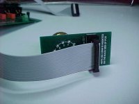
This build requires 2 IDC cables and matching connectors.
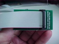
Cable #1) Usually 3 to 5 inches - Goes between the main PCB and the IO. Cable length depends on your choice of chassis
Cable #2) Usually 20 + inches - Goes between IO board and the front panel of the chassis. Again the overall cable length depends upon your choice of chassis.
I hope this clears your confusion.
Hi Carl,This build requires 2 IDC cables and matching connectors.
Cable #1) Usually 3 to 5 inches - Goes between the main PCB and the IO. Cable length depends on your choice of chassis
Cable #2) Usually 20 + inches - Goes between IO board and the front panel of the chassis. Again the overall cable length depends upon your choice of chassis.
I hope this clears your confusion.
I'm also interested, could you please post a link where we can buy them, thanks
Hi Carl,
I'm also interested, could you please post a link where we can buy them, thanks
DigiKey is a good source. EBay surprisingly is a very good source. And of course you could always build them yourself. EBay sells a kit of parts.
You are looking for 20 pin (ie: 2 x 10) IDC ribbon cables with a 2.54mm pitch. I don't have a specific part number handy. Pricing tends to move around on these.
Last edited:
Thanks Carl, may be someone who already bought them could post a link??DigiKey is a good source. EBay surprisingly is a very good source. And of course you could always build them yourself. EBay sells a kit of parts.
You are looking for 20 pin (ie: 2 x 10) IDC ribbon cables with a 2.54mm pitch. I don't have a specific part number handy. Pricing tends to move around on these.
Thanks!This build requires 2 IDC cables and matching connectors.
Cable #1) Usually 3 to 5 inches - Goes between the main PCB and the IO. Cable length depends on your choice of chassis
Cable #2) Usually 20 + inches - Goes between IO board and the front panel of the chassis. Again the overall cable length depends upon your choice of chassis.
I hope this clears your confusion.
I'm finding several parts, like the aluminum electrolytic capacitors (UES1V101MPM), to be out of stock at mouser and digikey. I found a few on arrow.com, but not all of them and it seems like many are back-ordered until Feb 2019. 🙁 Looks like I'll be waiting a while.
UES1V101MPM - Nichicon Radial Bipolar Capacitor
BD Enterprises has them and at a good price! UES1V101MPM
BD Enterprises has them and at a good price! UES1V101MPM
UES1V101MPM - Nichicon Radial Bipolar Capacitor
BD Enterprises has them and at a good price! UES1V101MPM
Thanks!
I guess my DuckDuckGo skills are failing me.
Cheers
Peter
- Home
- Source & Line
- Analog Line Level
- Doug Self Preamp from Linear Audio #5