A little story on my progress in TDA1541A DAC building.
I modded two Red Baron PCB to accept 50 Hz DEM mod and used them with Ian Canadas I2S to PCM converter in balanced mode and with passive I/V converter. This immediately bettered my, uptil now , preferred DAC with Ian Canadas FIFO and dual clock with isolator and custom designed I/V converter.
I had to dismantle it again as it was kind of a rats-nest construction and I want to put it in a nice box with remote vol. control etc.
So I had a third red baron pcb and I just got two pcb from ryanj with ecdesigns version of a I2S to Simultaneous converter (worked perfectly first time , thanks ryanj!) and I wanted to make a dac I could use , while building the balanced dac (it also needs to have 4 channels, as I want to make a digital corssover for future subs).
The dac was unmodded (besides 1uF acrylic SMD capacitors for DEM decoupling) and had the original single MOSFET I/V converter. Hmmm good but not great. Then I switched to passive I/V converter and I got a step closer, but not enough. I then modded it with 50Hz DEM and , wow, what a difference! This is a very good mod especially when you run the TDA1541A in simultaneous mode... Spaciousness and perspective is much better and the there is black darkness in the space between and behind instruments, so you can easily hear the recorded rooms response to the instruments..
The output from the passive I/V is too low for my amps , and I did not have a good enough preamp to deal with that, so I desided to try to mod. my TDA1543 I/V converter to work with TDA1541A. It was rather an easy mod and now I had plenty of output to my amps. Comparing the passive I/V to the modded active I/V, @ the levels that the passive could obtain, showed that the active was at least on pair with the passive solution. I had to turn down the digital vol quite a lot for the active I/V and I get lesser resolution that way. When I turn up the vol. the active performs even better.
The active showed me, when the digital vol was turn way down, that there was some noise overlaying the weak signals. Most of it was probably quantization noise, but when I added 100nf smd parallel to the 100 uF DEM capacitors, it was reduced, so I would recommend that.
Both the MOSFET I/V and the modded I/V (also a non-feedback circuit) have way lower distortion figures than the passive solution (FFT analyzer result)....Makes one wonder ...........
Concerning the I/V stage: I like MOSFETS and especially JFets as input devices and prefer them to bipolar, but in the event of an I/V converter bipolar are IMHO much better. They shine when they are used as current operated devices (that is their nature).
I hope this can be used as inspiration for others, but it is only my personal observations and of course subjective..😱
Hi Koldby,
Could you please upload some pictures, how you modified the Red Baron pcb? I would like to avoid modding my one and only RB5 pcb, thats the reason why I go for Ryanjs pcb. But if the modification looks easy maybe I try it.
Which type of 100uF elko are you using?
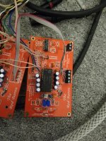
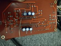
Modding the Red Baron pcb is very easy. Just put 4 of the 100/25 v caps on the component side and the rest , 3 pcs, on the copper side. There are exactly room for soldering the caps. The caps are Nichicon KA series .Hi Koldby,
Could you please upload some pictures, how you modified the Red Baron pcb? I would like to avoid modding my one and only RB5 pcb, thats the reason why I go for Ryanjs pcb. But if the modification looks easy maybe I try it.
Which type of 100uF elko are you using?
If you have a newer Red Baron, there are jumpers for changing it to simultaneous mode, else you have to cut some traces here and there 🙂
Attachments
Im doing this mod to my AyA DS, will report if it’s an improvement or ???
Bit of a hassle to install the 100uf caps due to space limitation. Oh Im using Oscons
as I have them already.
Bit of a hassle to install the 100uf caps due to space limitation. Oh Im using Oscons
as I have them already.
Thank you, Koldby!
I have the latest version of RB, the 5th edition, I can switch to simultaneous mode with jumpers. But the most important difference is that the dem capacitors intended to be only smd parts, therefore there are no wholes for the pins and the "copper" side can not be used to accommodate capacitors. So there is no place for the 100u-s. Have to seek another option.
I have the latest version of RB, the 5th edition, I can switch to simultaneous mode with jumpers. But the most important difference is that the dem capacitors intended to be only smd parts, therefore there are no wholes for the pins and the "copper" side can not be used to accommodate capacitors. So there is no place for the 100u-s. Have to seek another option.
Hi Guys
Ok fired my dac up & prelim it sounds quite nice still letting the caps burn in etc but notice that there’s a low level cracking sort of sound on quiet passages. Sounds similar to AM radio when we’re tuning to get the channel spot on. Any ideas the cause of this ?
Ok fired my dac up & prelim it sounds quite nice still letting the caps burn in etc but notice that there’s a low level cracking sort of sound on quiet passages. Sounds similar to AM radio when we’re tuning to get the channel spot on. Any ideas the cause of this ?
Hi Guys
Ok fired my dac up & prelim it sounds quite nice still letting the caps burn in etc but notice that there’s a low level cracking sort of sound on quiet passages. Sounds similar to AM radio when we’re tuning to get the channel spot on. Any ideas the cause of this ?
Sounds like you're getting current leakage through the oscons. You'll need to use a low leakage cap like the Nichon KA series with a voltage rating of 25V.
Thought Oscon are suppose to be low leakage. There’s someone here whose also using Oscon but didn’t hear him saying he’s got issues.
Thks Ryan
Thks Ryan
Polymer caps are high leakage for sure, much higher than normal 'lytics but this isn't an issue in their normal application which is power supply decoupling.
Thks Abrax but can it be so drastic as to cause this ?
It’s only happening on 1 channel btw. Will recheck soldering joints.
Many thks
It’s only happening on 1 channel btw. Will recheck soldering joints.
Many thks
Sounds like you're getting current leakage through the oscons. You'll need to use a low leakage cap like the Nichon KA series with a voltage rating of 25V.
Isn't the UKL series the low leakage one?
eg UKL1E101KPD1TA Nichicon | Mouser United Kingdom
I met the similar situation as I modified the CAP at analog region(decouple or couple)
I used to use the NOS caps like roe sic-safco......thus I blame for it's age.
But the sound will getting better and better with burn in.
There is once that is so worse that I thought it might be broken somewhere,but after 2 more
days the phenomenon went away and never happened.
Maybe it's totally different situation here
But I do agree the leakage is the root cause of it
You're right, they definitely have lower leakage (3uA vs 0.2uA at rated voltage).
I used UKA because this is what John recomended:
Hi weissi,
TDA1541A is placed in I2S mode by connecting pin 27 to +5V, pin 4 has nothing to do with this. TDA1541A can be placed in simultaneous mode by connecting pin 27 to -5V. The pins 1 ... 4 now get a different function.
I already mentioned that this will happen in my previous post and why this happens (100uF caps need to be charged with the small bit currents). With my prototype distortion was gone after a minute or so using 100uF /25V Nichicon UKA caps or caps with a higher voltage. Do -not- use 16V capacitors, it is best to have a large voltage margin for lowest leakage current, this will also ensure faster charging with low bit currents.
TDA1541A performs -very- poorly with I2S because:
Critical sample timing signal has to be extracted from WS and BCK while the I2S stream produces continuous ground-bounce. This causes trigger uncertainty and deterministic on-chip jitter.
The permanent I2S stream causes extra on-chip switching noise.
The 0111111111111111 to 1000000000000000 change around the extremely critical zero crossing area will increase low level distortion.
I experimented for almost a decade with the TDA1541A. With I2S there comes a point where sound quality doesn't get better no matter what is tried.
TDA1541A performs a lot better when driving it in simultaneous mode with 25% data density (16 bits data followed by 48 bit silence). This also reduces average switching noise during each sample by up to 75% .
Sample timing is generated by a dedicated signal (LE) and can be generated when the data stream has -stopped- for 16 bits and ground-bounce is almost zero. This leads to lowest on-chip trigger uncertainty and lowest on-chip jitter. This is -very- important with these kind of chips that switch relatively slow (approx. 7 MHz max. switching frequency).
TDA1541A performs best by far when driving it in signed magnitude mode because:
Low level distortion and switching noise will be reduced significantly as only few bits change around the zero crossing and the monotonicity of the DAC improves.
If one is concerned about channel matching (this causes ever so slight even order harmonics distortion that is not objectionable) following can be done:
Put 100K ... 1M multi turn trimmers in parallel with each 150R passive I/V resistor and sum both outputs with say 1K resistors. Then trim for best channel / segment matching.
An externally hosted image should be here but it was not working when we last tested it.
Can’t wait for the 100uF
So try to modify to0.1uF and keep the0.1uF first.
The change is obviously.but the treble is a little bit too much
Maybe cause by the decouple caps can’t follow
Echo and harmonics are completely and neat!
Last edited:
I had the same issue initially. It has gone after a couple of hours. I used Nichicon Muse 100uF/25V. Pictures are several pages back.Thks Abrax but can it be so drastic as to cause this ?
It’s only happening on 1 channel btw. Will recheck soldering joints.
Many thks
I've just been comparing (on paper) a number of caps that are immediately available to me as I would have to wait on the Nichicon KA. So can confirm there are many with about the same leakage as the KA eg. Panasonic FM & NHG, Nippon Chemicon KY, Rubycon YXJ, Elna RE2 & RJB
The KL are larger diameter (8mm cf 6.3mm for KA) so you can not group them as close to the pins; also ripple current is higher for KL.
•Still something confuse me. I found that EC change to use 50Hz about #6069.
Before that he try the higher freq DEM which I can get the point then.
The DEM accuracy seems to be better with high freq oscillator. But the low freq. modify do get better, why??
That he mention about facing some “DEM problem". But I wonder to know why it won’t cause some effect as it drop into the audible region.
I know this might discussed before but I’m sorry that I just can’t find it.
the other question is it seems to use two resistor at pin16 and pin17 connect to pin15
why change two a single registor?
Last edited:
Guys would using bipolar caps be better or ???
Probably have too much leakage.
I think this is very important since the currents involved are very small and this is proved by the need to wait several minutes to charge up 100uf.
UKL are the lowest leakage ones I could find and they are larger diameter but since the dem frequency is 50Hz instead of 175-200Khz, I do not think the need for longer tracks to them is a problem.
My dual 1541 pcbs will arrive at the weekend so I hope to report back next week on the results with the UKL caps.
- Home
- Source & Line
- Digital Line Level
- Building the ultimate NOS DAC using TDA1541A