IF it's for the decoupling usage
Maybe shunt to ground from PIN15 VDD- (-15V) ?😛
So
There's a DEM oscillator about 50Hz inherent from 1541?
It's confusing as I refer to this
https://bgaudioclub.org/gallery/albums/userpics/11619/HtP_Dem_Description.pdf
It seems need external oscillator to do the DEM.......😕
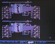
We've crossed wires and you have confused yourself. Just follow the schematic on post 6077, 14x100uf dem decoupling caps, +ve to ground and 1uf oscillator cap for the dem clock on pins 16/17, with the 12k resistor to -15v from pin 17.
The internal dem oscillator frequency is determined by the cap on pins 16/17 and ECD have found that using a 1uf cap forces it to oscillate at 50Hz but this also requires all the decoupling caps on the 14 pins to be 100uf in order to filter out the 50hz ripple.
At the original designed dem frequency of about 200Khz, the dem caps were all 0.1uf because the ripple can be removed by this value. Some recommend synchronising the dem clock to WS or BCK but a paper I read on this advised not to but to use random, also called stochastic, techniques.
So you can't use a 1uf cap and not also change all 14 dem decoupling caps to 100uf.
Decoupling in the thread refers to the dem decoupling caps of 100uf, not the power supply for which I am using Os-con very low impedance electrolytics and .22uf ceramics (damped with a dab of hot glue)
Last edited:
Allow me to pile on! the jump resulting from sim format is similar to the additional jump then attained by using John's 100uF DEM cap recommendation..
I suspect you have little to worry about as you build some amazing DACs.
Well, half-jealous really, as I own a Mosaic DAC 😎
The DAC building adventure has been very entertaining so far, though my physical execution lets a lot to be desired! 😀
Cheers,
M.
PS: damn! I don't know why the pics get upside down...
Attachments

I’ve just read two paper by RUDY J VAN.
A monolithic 14 bit D/A converter
And
Dynamic elements matching for high accuracy monolithic D/A converters
Frankly speaking I can just barely understand half.😛
But the accuracy seems according to the delta t and delta I
The DEM switching time(clock?) and current variation (cause by process).
So ....why reduce the clock frequency will make it better?
Although I have seen some explanations.But still don’t get it.🙁
Sorry Guys
Need to reconfirm re 100uf caps, do we orientate with negative leg of the caps to ground or ???
Thks
Need to reconfirm re 100uf caps, do we orientate with negative leg of the caps to ground or ???
Thks
Hi sumotan,
!00uF/25V caps, plus (+) connects to GND (0V). Minus connects to the pin of the TDA1541A.
Reason: the DC voltage on the 14 TDA1541A decoupling pins is negative (-12 ... -14V typical) with respect to GND.
1uF film cap between pins 16 & 17, 12K resistor between pin 15 and pin 17.
See attached schematic.
Sorry Guys
Need to reconfirm re 100uf caps, do we orientate with negative leg of the caps to ground or ???
Thks
!00uF/25V caps, plus (+) connects to GND (0V). Minus connects to the pin of the TDA1541A.
Reason: the DC voltage on the 14 TDA1541A decoupling pins is negative (-12 ... -14V typical) with respect to GND.
1uF film cap between pins 16 & 17, 12K resistor between pin 15 and pin 17.
See attached schematic.
Attachments
Oops sorry. My dac right now has 14 0.1 uf smd caps soldered in,
can I leave the caps as is & solder in parallel the 100uf caps ?
Thanks again
can I leave the caps as is & solder in parallel the 100uf caps ?
Thanks again
I know jealousy is a sin, but man, you are making us jealous with those comments. 😀
We, TDA1541 virgins, must wait until our digital guru comes with a complete working DAC.
Meanwhile, I am perfecting my TDA1543 DACs, the "scrambler-interpolator" and the "dual-mono" DACs, that may be less detailed and noisy but that surely have dinamics and impact to spare...
I confirmed what guru anticipated, that sometimes the digital chain of the dual-mono DAC refuses to ride more than a certain number of DAC chips- In my case I have only a couple of successful 8 chip towered DACs. The rest seem comfortable with only 4 chips tower DACs, so I am building a two module DAC each with 4 chip towers, in parallel. 😎 If that goes OK, I think I will expand the idea, but, will I get more bit depth???
Cheers,
M.
Yes. I am thinking to apply sim format to discrete dac (now running on I2S). I am almost positive that will be better sonicaly... I will check this and report.
But my simultaneous cpld interface is just 14bit / 16 bit option. I dont have 24bits length word. So I will "cut" the r2r network to 16 bits and probably override the inverter on 1st bit because I think that is already inverted in cpld routine...
Last edited:
Oops sorry. My dac right now has 14 0.1 uf smd caps soldered in,
can I leave the caps as is & solder in parallel the 100uf caps ?
Thanks again
I dont think it will hurt if you leave them in.
I’ve just read two paper by RUDY J VAN.
A monolithic 14 bit D/A converter
And
Dynamic elements matching for high accuracy monolithic D/A converters
Frankly speaking I can just barely understand half.😛
But the accuracy seems according to the delta t and delta I
The DEM switching time(clock?) and current variation (cause by process).
So ....why reduce the clock frequency will make it better?
Although I have seen some explanations.But still don’t get it.🙁
Maybe its to do with noise from the internal dem clock affecting the conversions?
Incidentally, I read on another website where it was stated that the dem clock is divided by 4 in 1541, which means you cannot use WS on a NOS dac (44k) as it would result in the dem ripple being 11k Hz so in the audio band.
Grundig use this method but with in OS mode, so the dem ripple is 44 or 88Khz. I was going to use their dem clocking method until I read this, the paper about stochastic clocking and then ECD came up with their 50Hz clocking and saved the day.
Thks Ryan , its not like decoupling with additional bypass added, hence
my concern.
Cheers
No problem, I believe Walter kept his 1u film caps in place when he applied the mod.
1uf vs 0.1uf is a great difference Ryan. My worry is because of the low esr & value of the smd caps, will all the voltage be dumped via these caps & if in doing so those 100uf caps will not function fully. Perhaps I might be too hysterical over this but having said that it’s gonna kill the circuit board if If have to redo the soldering.
Thks again
Thks again
1uf vs 0.1uf is a great difference Ryan. My worry is because of the low esr & value of the smd caps, will all the voltage be dumped via these caps & if in doing so those 100uf caps will not function fully. Perhaps I might be too hysterical over this but having said that it’s gonna kill the circuit board if If have to redo the soldering.
Thks again
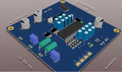
I see your concern.
If you do destroy your PCB, ill give you one of these i've been working on:
Attachments
So very nice of you Ryan. Thank you so much.
Hey before you know it everyones gonna ask for 1 from you ya . Lol
Hey before you know it everyones gonna ask for 1 from you ya . Lol
So very nice of you Ryan. Thank you so much.
Hey before you know it everyones gonna ask for 1 from you ya . Lol
Gotta make sure it doesn't oscillate first! 😉
I see your concern.
If you do destroy your PCB, ill give you one of these i've been working on:
Are you going to use the same kind of cascading regulators as D2? I think many of us found that difficult to get our heads around.
Should probably move this to a new thread? or one of your existing ones?
Yeah going to keep the "zener string", but i've changed a few things to make it less confusing and easier to implement. I'll start a new thread soon, maybe get a list going to see if its worth doing a big order to get the price down as low as possible - 4 layer pcbs aren't too cheap in small runs.
- Home
- Source & Line
- Digital Line Level
- Building the ultimate NOS DAC using TDA1541A