Very good.. Move the .1uf's before each bridge or add them? Thanks!
Move
The certainly don't hurt where they are, and likely help (both the 0.1uF directly across the line and the other one in series with a 1 ohm resistor).Very good.. Move the .1uf's before each bridge or add them? Thanks!
I say add.
ETA: Move the 0.1uF circuitry on the right over to the PCB of the device(s) being powered, as well as adding to the secondary coils.
Last edited:
You need new PCB for parallel circuit.
Did u do PCB for schematic from post #23 ? or maybe u try this schematic in live?
Prasi, okay I got it. I got all the resistors and diodes installed.Hi Jonathan,
yes, all my resistors were 1/4W, you could use 1/2 W for R11.
For the zener, I used a 1W zener that I had in my parts bin, you could use 1/2 W.
The hole near C6 is a 'via' used to change layer of the trace from bottom to top.
Hope this helps.
regards
Prasi
other parts recommendations.
1. good quality film cap for C8
2. NPO/C0G for C2
3.For R11, you can even fit 1-2W if you can find a small enough resistor package.
Now the age old question, capacitors, especially the electrolytics. Should I just use whatever is low ESR and of good quality, or is there a benefit of using 'audio' cap here? I am looking at Rubycon ZL, ZLH, Panasonic FC, vs Nichicon FW on the audio side. Please let me know what you think, thank you. 🙂🙂
Last edited:
Hello Jonathan,
I generally use good quality industrial caps for rail decoupling.
Only for bootstrap and nfb , i 'try' to use audio grade cap. Most of the time I end up using whatever I have and whatever fits the pcb. 🙂 I have limited access to good caps that people often talk about and not to forget, limited budget.
Regards
Prasi
Last edited:
My gainclone base on apex schematic. Thank you Apex.
Hi Bimo,
Where is the input points and Speaker Left and Right is there. But no GND for Audio.
Can you share the Details for this
Regards,
Nandhakumar
BOM List Plz
Hi Prasi,
Plz share us the material list., i like to try your design.
Thanks,
Nandhakumar
Hi Prasi,
Plz share us the material list., i like to try your design.
Thanks,
Nandhakumar
assembled 1 channel to see how it sounds. powered up fine without glitches first time.
Sounds very good on test speakers, used a opa2134.
here are the pics. Thanks Mr. Mile for the circuit. Am I the first one to test this particular ckt?
I might put this one in my boom box that currently uses a dayton DTA-2 class T amp.
regards
Prasi
Hi Prasi,
Do we need to fill that hole near C6.
Thanks,
Nandhakumar
Do we need to fill that hole near C6.
Thanks,
Nandhakumar
Hi Jonathan,
yes, all my resistors were 1/4W, you could use 1/2 W for R11.
For the zener, I used a 1W zener that I had in my parts bin, you could use 1/2 W.
The hole near C6 is a 'via' used to change layer of the trace from bottom to top.
Hope this helps.
regards
Prasi
other parts recommendations.
1. good quality film cap for C8
2. NPO/C0G for C2
3.For R11, you can even fit 1-2W if you can find a small enough resistor package.
PSU
Hi Bender460,
can you post the PSU image and design.
Thanks,
Nandhakumar
Hi Bender460,
can you post the PSU image and design.
Thanks,
Nandhakumar
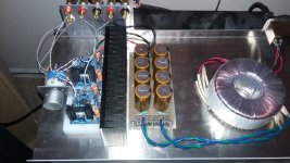
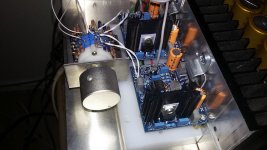
Getting going on a APEX Super Gainclone. Purchased some boards and parts from prasi a while back. He put together a great kit for me. Really really good. Thank you prasi.
Second pic is of the power supply that will be next to put together. Hopefully in the next couple weeks I'll post pics of a finished amp.
Hi Prasi,
Do we need to fill that hole near C6.
Thanks,
Nandhakumar
its a via. VIA – Via Hole – Eurocircuits
15V regulators supplying power to OPA2134 should be enough I guess? Why put +-18V, the maximum allowable voltage of the op amp?
The only difference in V+ V- I see is slightly improved THD, that will be masked by LM3886 anyway.
The only difference in V+ V- I see is slightly improved THD, that will be masked by LM3886 anyway.
Last edited:
Probably because apex wanted less heatsinking for the regulators.
Op amp when specified to run at 18v, it should run reliably and regulators make sure they are supplied with 18v.
Note That rail voltage is used to simply requirements of everything{LM3886+OPA2134}.
Op amp when specified to run at 18v, it should run reliably and regulators make sure they are supplied with 18v.
Note That rail voltage is used to simply requirements of everything{LM3886+OPA2134}.
Hi Mr.mile... i am going to use 22-0-22vAC trafo(+/-30vDC) for Apex gainclone Ver:1 .
So what would be the zener voltage rating instead of 16v?
I would be grateful to you if you help me. Thnks.
So what would be the zener voltage rating instead of 16v?
I would be grateful to you if you help me. Thnks.
HELP!!
Sir mile please response... my transformer is 22-0-22vAC (+/-30vDC).
what would be the zener diode voltage rating instead of 16v?
I am saying about apex lm3886 gainclone ver:1
Zener 16V is for turn on delay but your PSU voltage with 2x15vac is too low, just use 5V6 zener instead 16V and that will unmute LM3886.
Sir mile please response... my transformer is 22-0-22vAC (+/-30vDC).
what would be the zener diode voltage rating instead of 16v?
I am saying about apex lm3886 gainclone ver:1
- Home
- Amplifiers
- Chip Amps
- LM3886 Schematics + PCB