Short or what?//
Yes likely to be a short somewhere. Start by doing a resistance check from the Red speaker terminals (chassis ground) to the centre pins of Q1 and Q2. A zero reading (a short) will be bad.
Have a look down the back of the board and make sure there isn't a lead/wire touching the chassis etc.
Do both Q1 and Q2 warm up or just one or the other. Can you measure the bias at all before the PSU slumps?
Can you post pictures please?
Alan
When i power up everything works fine ..the leds glow and the speakers make sound...but when the boards warm up the psu crashes and cycles on and off.
tested seperately both boards do the same thing
tr4ied an other psu and it just crashes until unpluged and replugged in
i checked proper installation of all components and it all seems good
any thoughts on where to go next
thanks Harvey
Yes likely to be a short somewhere. Start by doing a resistance check from the Red speaker terminals (chassis ground) to the centre pins of Q1 and Q2. A zero reading (a short) will be bad.
Have a look down the back of the board and make sure there isn't a lead/wire touching the chassis etc.
Do both Q1 and Q2 warm up or just one or the other. Can you measure the bias at all before the PSU slumps?
Can you post pictures please?
Alan
Starting up my build on the ACA 1.6 version. I have more then enough NOS Silmic 2200uf/35v that can drop in to where the output coupling position(3300uf/35v) is would this be unadvised and just be a outright bad idea? I wish to make this amp the best that it can be within reason
You could use CDE 10,000uF / 35V SLP (fits perfectly on a PCB) and 2.2uF polyester or polypropylene film cap in parallel. That would be much better than any 2,200uF cap, for a speaker sound coupling duties.
The C2 can also have around 0.068 - 0.1uF polypropylene cap in parallel.
C3 could be a film capacitor, but Silmic II is a very good cap already; maybe just place a 2,200nF polystyrene film cap in parallel to it.
The trim-pot can be mounted orthogonally on the PCB so that you can trim it just by removing the top cover.
The pseudo-bridged (mono-block) switch at the back can use both of its contacts in parallel, to reduce contact resistance (nit-picking, but why not if it's there already...to be used...)
The R1 can have a provision for a 10dB/13-14dB gain option, by installing two resistors in parallel (and then choosing one that suits your needs better): 22K and 68K. If you decide to do this, follow with the same resistors' pair combo for the pseudo-bridged (mono-block) resistor.
A dangerous thing would be to fit the SMPS inside the ACA... bring the mains voltage inside the ACA (ouch, lethal!!!! - not recommended if you do not know what exactly needs to be done to ensure safety is in place!!!)...... but.... also shorten the DC bus wiring
")
You could also replace the Litz hook-up wire with something "exotic", if you believe that the wire makes a difference...
Last edited:
Do you think these are fakes? Reichelt is a big German company.BigCheese, do you have spare 2SK170? They are really difficult to procure and most sources you will find are counterfeits or fakes. More info here (Replacement For Toshiba 2SK170/2SJ74
2SK 170: JFET, N-CH, 40V 20mA, 0,4W, TO-92 bei reichelt elektronik
He did. It is most clear in the third picture. It is a nylon spacer and is a clear color, not aluminum one like some of the other ACA kits. I ordered 2 sets as monoblocks so I received one of each kind.
Best,
Anand.
My eyes are not like they used to be.... getting old... might need a loupe soon...
Hi Mooly
Both sides of the amp are heating up now and they have that 24 volts on Q2 and R7. All that is missing is the elusive sound.
Thanks again.
Ed
Try the method I mentioned of using your meter on a low AC volts range to confirm that both channels are in fact seeing the same AC input voltage.
If you need a test tone (low bit rate MP3 is fine) I can post one here.
Always possible that they have died, but if you can change the bias all 4 are one way or another working. I would print Zen Mod diagram in post 5516 and write every measured voltage on it and compare.....I am about to give up on these Q3 and Q4 and put in new ones.
Amp Camp Amp - ACA
Do you think these are fakes? Reichelt is a big German company.
2SK 170: JFET, N-CH, 40V 20mA, 0,4W, TO-92 bei reichelt elektronik
I'm afraid that Reichelt sell some fake parts.
Last edited:
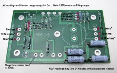
Boyz , for troubleshooting purposes , always include some measurements , information of exact schematic (few schm. iterations are there) to be sure about nomenclature , and few well made pictures
example of important measurement points , you can use it as general guide (parts nomenclature not by Papa's schematic!!):
I built the ACA's as well to confirm that the sound of two transistors clapping is indeed outstanding. They don't have any troubles driving my 4ohm flat-ish impedance speakers, within their capabilities, of course. My voltage readings are (exactly) the same as what you posted.
The main trouble I am having is the ringing at the clipping point that sounds quite unpleasant; I'd like a softer / cleaner recovery. With this in mind, do you think that a 5.6V zener across C2 would help, aka "Alep CCS modification.pdf" (attached)? The voltage across the ACA's C2 is the same as in the pdf example... so I'd expect no ill effect - only a cleaner recovery? Am I right??
Thanks
Attachments
Try the method I mentioned of using your meter on a low AC volts range to confirm that both channels are in fact seeing the same AC input voltage.
If you need a test tone (low bit rate MP3 is fine) I can post one here.
Here is a tone anyway. 440Hz. There is a 10 second fade in and fade out. Set your volume control to give say 6 volts AC as measured at the speaker output (NO speakers connected) and see what level of input voltage you measure on the top of R11 (audio input).
You should read around 1.64 volts rms at the input for 6 volts rms output voltage (no load attached).
Attachments
I built the ACA's as well to confirm that the sound of two transistors clapping is indeed outstanding. They don't have any troubles driving my 4ohm flat-ish impedance speakers, within their capabilities, of course. My voltage readings are (exactly) the same as what you posted.
The main trouble I am having is the ringing at the clipping point that sounds quite unpleasant; I'd like a softer / cleaner recovery. With this in mind, do you think that a 5.6V zener across C2 would help, aka "Alep CCS modification.pdf" (attached)? The voltage across the ACA's C2 is the same as in the pdf example... so I'd expect no ill effect - only a cleaner recovery? Am I right??
Thanks
don't use force , use a bigger hammer .
build bigger amp , if you care about clipping
well, for Aleph CCS , zener mod is already confirmed to soften a clipping
however , I experienced that my ears are not happy before clipping point of Aleph CCS
so , two ways from there - either build bigger Aleph , or acquire speakers better using power of existing Aleph
example - in my workshop , I'm damn happy with 3W feeding RCA LC1B in MLTL boxes , while for Tannoys in my living room (OB with Beyma 15" bass helper , so diving under 4R down) I'm happy with 10W
However, I just noticed that one of the bags contains leftovers - 4 small nuts and 6 small flat washers. I'm not aware of anyplace that they should have been used, especially since their quantities differ. Ideas?
I had the exact same leftovers. They are just that...left over.
Do you think these are fakes? Reichelt is a big German company.
2SK 170: JFET, N-CH, 40V 20mA, 0,4W, TO-92 bei reichelt elektronik
I really wouldn't know. If they are not fake, then that would be awesome! Can you share that link into the thread I posted earlier? They will be quick at detecting issues and some would even buy them and test them to determine their authenticity if there is a chance that this is a genuine source!
Please, head over to Replacement For Toshiba 2SK170/2SJ74 and share that link.
Best regards,
Rafa.
Having a think here.
Seeing that a few problems arise on new builds and not every one reads a circuit diagram (no shame it that), I wonder if a simple 'No Power' resistance checker would be useful?
One; for checking for obvious faults before switching on for the first time when the assembled board is mounted in the heatsinks and
Two; for first line checking of the active devices without the need to power up and measure voltages.
Something like this perhaps? Hope it fits in with Mr. Zen's needs too... ;-)
Alan
Should of added, the readings are a compilation of a couple of working ACA boards and 3 different digital meters, so 10% either way maybe.
Attachments
Last edited:
Well, it has been confirmed that the Reichelt stock is, indeed, fakeDo you think these are fakes? Reichelt is a big German company.
2SK 170: JFET, N-CH, 40V 20mA, 0,4W, TO-92 bei reichelt elektronik
.Just one note here: I did the same and soldered Q4 reversed on one of the PCBs.... I am about to give up on these Q3 and Q4 and put in new ones. Can I use 2SK170 to replace the K170 on Q4?...
It heated up considerably before coming loose, and it took several attempts at sucking up the solder / heating / pulling, rinse and repeat this for the better part of 20 minutes with both me and dad heating and pulling the transistor.
It really took some beating and abuse.
In the end, it worked flawlessly! So, at least mine, was really resilient. Maybe yours is alive and well and there are other problems? Hope so! Best regards,
Rafa.
Do you think these are fakes? Reichelt is a big German company.
2SK 170: JFET, N-CH, 40V 20mA, 0,4W, TO-92 bei reichelt elektronik
I don't know if freight is OK, but nacsemi.com sells the original LSK170D in small quantities (from 1ct.)
- Home
- Amplifiers
- Pass Labs
- Amp Camp Amp - ACA