Oops, post #419 was made before #418. I edited my broken(all the time..) english and it made your reply to my post before my post.. Funny.
Maybe we can brodean the usable SITs this way?
Please let me know why or why not this would work... 🙂🙂 I am a dumb builder..
The F in DEF stands for Follower, and your circuit has voltage gain.
The F in DEF stands for Follower, and your circuit has voltage gain.
Maybe nothing is free, what does it lose in return..... damping? 😕
Of course I do not understand at all, why DEFiSIT is a follower and my circuit is not....... 🙂
Last edited:
go to FW site , under articles , look for pdf titled art_sony_vfet_pt1
edit: here it is : http://www.firstwatt.com/pdf/art_sony_vfet_pt1.pdf
read from start , but especially observe second circuit iteration in article
edit: here it is : http://www.firstwatt.com/pdf/art_sony_vfet_pt1.pdf
read from start , but especially observe second circuit iteration in article
Last edited:
Wow it's the same as CSX-2, replacing 2SJ28 with IRF9240. 
"They may look like Common Drain connections (followers) but they are not, since the drive voltages provided by the transformer secondaries are floating – they are still Common Source amplifiers."
"In particular, it doesn't have much of a damping factor, and so don't expect a lot of control out of it."
...So already one of the three merits of DEFiSIT is gone .. 🙁
higher damping (X)
single ended harmonics (?)
power noise reduction (?)
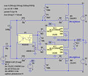
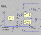
Your finding gave rise to an improvement idea. The first iteration is not so sensitive because the 2.5 V + 400 mV/A signal from Hall chip is attenuated to < 48 % by a resistor network. There is an option that increase effective signal to > 86% by DC shifting the opto using a voltage reference chip like the LM385-1.2 as attached. However, usability with the pucks still need further investigation.Hockey pucks , being sooooo wild beasts , simply can't be tamed with current sensing Hall IC , without resorting to additional amplification stage (in bias servo) ...
Attachments
As always,great tips from you 🙂
Check effective loading impedance seen by halls, it must be above 4k7....check it in dynamic conditions
Hate typing on wincraphone .... 🙂
Check effective loading impedance seen by halls, it must be above 4k7....check it in dynamic conditions
Hate typing on wincraphone .... 🙂
🙂
Even though we are no expert like Papa, we can always use the proven plug and pray method in LtSpice and avoid too many blown up parts.
Even though we are no expert like Papa, we can always use the proven plug and pray method in LtSpice and avoid too many blown up parts.
Last edited:
yeah .... gut feeling
per sims , comparison with (so called ) final Babelfish M25 sim , elevating optooupler for 1V25 , then increasing both Hall output resistors and gate-rail resistors ...... result is few times worst Iq stability ....... both in temp domain and rails change domain
so , gut ...... told me that Babelfish XA25 will stay with current mirrors in bias circuit
Hall chips - they simply demand additional gain stage , between them and opto(s)
in any case ..... idea was worth checking ; we are not in state Mu , in terms of scientific process (few steps back , few steps forth , one step back , few steps forth )

per sims , comparison with (so called
 ) final Babelfish M25 sim , elevating optooupler for 1V25 , then increasing both Hall output resistors and gate-rail resistors ...... result is few times worst Iq stability ....... both in temp domain and rails change domain
so , gut ...... told me that Babelfish XA25 will stay with current mirrors in bias circuit
Hall chips - they simply demand additional gain stage , between them and opto(s)
in any case ..... idea was worth checking ; we are not in state Mu , in terms of scientific process (few steps back , few steps forth , one step back , few steps forth )

🙂
Even though we are no expert like Papa, we can always use the proven plug and pray method in LtSpice and avoid too many blown up parts.
speaking of ......... I really can't say where I induced more gray poof smoke - in sims or in real life
Attachments
Yes, wrong approach. AC component became prominent while stable Iq needs the DC average.😀...... result is few times worst Iq stability ....... both in temp domain and rails change domain ......
Or some kind of LPF to attenuate the AC component.🙂Hall chips - they simply demand additional gain stage , between them and opto(s)...
Attachments
try the same with proper big Iq
then do step test for rails from zero to say 28V
then do step test for temp , from 25 to 65
second one of secondary importance , of course
just observe diff in Iq vs. rail voltage
for AC , you have that big 3m3
then do step test for rails from zero to say 28V
then do step test for temp , from 25 to 65
second one of secondary importance , of course
just observe diff in Iq vs. rail voltage
for AC , you have that big 3m3
The change of R18 and R19 from 2k7 to 18k hurt Iq stability vs change of Vcc. Adjusting Iq by loading with a 4k7 improves stability a bit. The addition of LPF improves dynamic Iq stability on asymmetric design like the attached SEF.
Attachments
nothing prevents you from trying the circ , then compare it with later ones ......
Yes, and I realized that I am struggling against not-so-sensitive speakers for this fun game, hence using the ridiculous aluminum tower. 🙁
So an Altec speaker is being traded with a friend of mine and many SITs are available for play. 2SK60 2SK82 2SK180 THF-51S......... 😀😀😀
Cheers
- Home
- Amplifiers
- Pass Labs
- Most Greedy Boy, of them all... or (there is no) DEFiSIT of Papa's Koans

