Well, yes, but......conventionally we imagine it flows from positive to negative, it doesn't really matter though... 😉🙂
Not sure how you deduced a direction from my comment?
It could have read either way.
Hello nigelwright7557..
My own power amplifier follows speaker return to star earth zero point between the psu caps and with volume at max with no signal appiled to it there is dead silent.
Ie no hum or buzz.
So agree with you there...
My own power amplifier follows speaker return to star earth zero point between the psu caps and with volume at max with no signal appiled to it there is dead silent.
Ie no hum or buzz.
So agree with you there...
I've always used high graded signal cabling and routed it away from the psu wiring and that's works for me.
I thought you were referring to Andrew's post about it flowing from 0V to negative, so it flows from the centre of the smoothing caps not back to itNot sure how you deduced a direction from my comment?
It could have read either way.
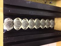
good spare batch of mosfets from a old project put on hold .. this was from a project made over 20 years ago with less experience ... hence the over use of heat sink compound 😀
the mosfets have never been used
the mosfets have never been used
Attachments
Last edited:
2nd Time Around
This article in glorious colour from Electronics magazine might be of interest to all you Maplin fans .... Look on page 48.
See: http://www.americanradiohistory.com/Archive-Maplin-Elrectronics/Maplin-Electronics-1990-12-01.pdf
the mosfets have never been used
This article in glorious colour from Electronics magazine might be of interest to all you Maplin fans .... Look on page 48.
See: http://www.americanradiohistory.com/Archive-Maplin-Elrectronics/Maplin-Electronics-1990-12-01.pdf
Attachments

Last edited:
This article in glorious colour from Electronics magazine might be of interest to all you Maplin fans .... Look on page 48.
See: http://www.americanradiohistory.com/Archive-Maplin-Elrectronics/Maplin-Electronics-1990-12-01.pdf
Hello thanks for the info .. I have already purchased the original magazine from ebay, but nice to have a scanned copy as been out of print for many years
Hello ..
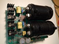
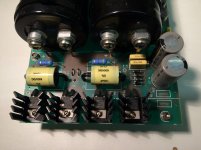
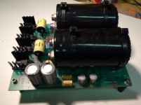
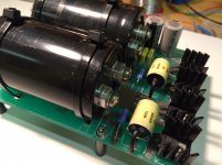
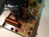
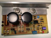
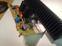
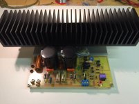
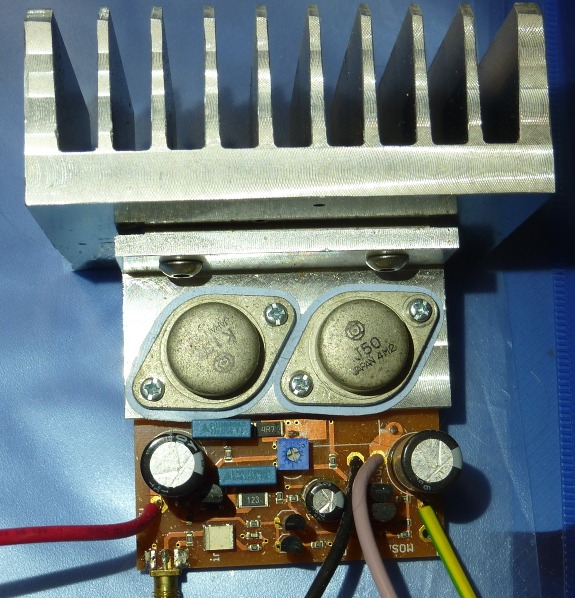
This is another version of the maplin mosfet amp I have been working on, basically the same circuit but with LED current source at the front end , and with BF470 / 469 driver transistors.
The power supply is mounted all on the same board with heavy duty spade connections and PCB tracks .. works well with no hum etc
Attachments
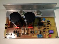
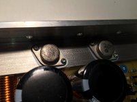
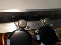
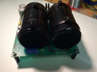
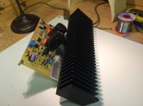
now with the heat sink mounted .. please note this has not been finally completed so the heat sink is just a trail fitment exercise .. but will most probably go with this set up
Attachments

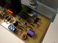
Nice, I attached a phono socket directly to the original amp boards, I don't know why it isn't done more often. Have you tried using Belleville washers for transistor mounting? Belleville washer - Wikipedia
Nice, I attached a phono socket directly to the original amp boards, I don't know why it isn't done more often. Have you tried using Belleville washers for transistor mounting? Belleville washer - Wikipedia
well done .. never knew there was such a thing as a Belleville washer ? thanks for the head up 🙂
Hello .. have not been around for a while as have been very ill .. but on the road to recovery, any way while at home I got bored so decided to develop the gerber files for the maplin mosfet amplifier as really fond of the design and sound quality .. retro years etc in my youth
Attachments
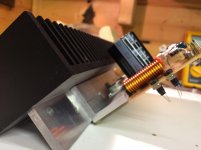
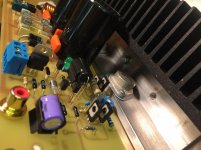
This thread reminded me, I reworked the Maplin amp using a custom smaller PCB - I had a stock of a few pairs of 2SK135/2SJ50's and the small signal transistors from way back to find a use:

The output inductor is under the board as are the gate protection diodes & zeners.
The output inductor is under the board as are the gate protection diodes & zeners.
I imagine from the layout and heatsink sizes, that there was no pretence that this version would still deliver 100W reliably .This thread reminded me, I reworked the Maplin amp using a custom smaller PCB .....
This thread reminded me, I reworked the Maplin amp using a custom smaller PCB - I had a stock of a few pairs of 2SK135/2SJ50's and the small signal transistors from way back to find a use:
The output inductor is under the board as are the gate protection diodes & zeners.
Hello Mark ... that is indeed small, did your newly designed PCB work all OK? just out of interest did you make any changes to the design and component values? or transistor types? just curious to know
Best regards
I imagine from the layout and heatsink sizes, that there was no pretence that this version would still deliver 100W reliably .
100W continuous, no I suspect not, but its adequate for normal use I think, I tend not to listen to pure sine waves at 100% level (dub reggae perhaps being an exception!). The boards were tested to 100W briefly to check stability, and are awaiting a nice case plus preamp.
- Home
- Amplifiers
- Solid State
- Maplin MosFET Amplifier GA28F construction thread