Hi
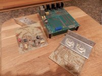
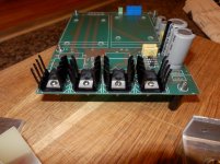
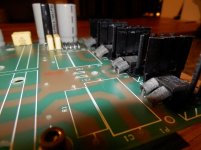
Please find a few pics of my new Maplin 100w Mosfet amplifier construction thread .. All parts are new old stock with original transistors, but all capacitors are new, just a little bit of nostalgia from the past !!
Both amps will be mono blocks ..
best regards Nick
Please find a few pics of my new Maplin 100w Mosfet amplifier construction thread .. All parts are new old stock with original transistors, but all capacitors are new, just a little bit of nostalgia from the past !!
Both amps will be mono blocks ..
best regards Nick
Attachments
-
 P6080039.jpg493.1 KB · Views: 2,890
 -
 P6080040.jpg403.1 KB · Views: 2,754
 -
 P6080041.jpg400.8 KB · Views: 2,662
 -
 P6080042.jpg365.3 KB · Views: 2,657
 -
 P6080043.jpg440.9 KB · Views: 2,537
 -
 P6080044.jpg357.9 KB · Views: 1,026
 -
 P6080045.jpg456.7 KB · Views: 829
 -
 P6080046.jpg313 KB · Views: 865
 -
 P6080047.jpg309.3 KB · Views: 822
 -
 P6080048.jpg471.3 KB · Views: 844
More pics
Hello
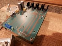
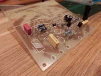
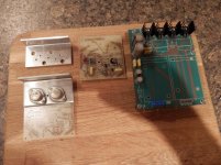
One power amp board nearly complete .. all new components etc
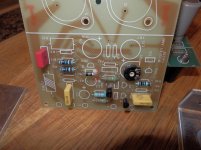
and one of the PSU board which is very rare
regards
NIck
Hello
One power amp board nearly complete .. all new components etc
An externally hosted image should be here but it was not working when we last tested it.
An externally hosted image should be here but it was not working when we last tested it.
An externally hosted image should be here but it was not working when we last tested it.
and one of the PSU board which is very rare
An externally hosted image should be here but it was not working when we last tested it.
regards
NIck
I've got the original article here if you would like to add it.
Me too.
Just bought one of these amps off ebay about 2 weeks ago.
It wasn't even built up, still in kit form.
So I built it up and it worked first time.
Sounds really good.
An externally hosted image should be here but it was not working when we last tested it.
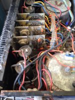
Here's another Maplin amp I bought and repaired.
An externally hosted image should be here but it was not working when we last tested it.
An externally hosted image should be here but it was not working when we last tested it.
Hi
I am having some new PCB's being made, 2 oz bare copper Fr4 boards .. I generated my own gerber files to update the original layout.
If anyone wants any let me know .. as the examples on ebay are over priced, I can make them very much cheaper with modern components .. however I do have a stock pile of the original transistors ... luckily for me
regards
Nick
I built my first one around 1980.
It worked fine but wasn't loud enough for disco.
So I bought the 225WRMS bipolar amp kit and that was great.
I have just redesigned the 100 watt mosfet amp to work with hexfets.
The circuit is basically the same but with source resistors, irfp240/9240 and a Vbe multiplier with thermal feedback.
It worked fine but wasn't loud enough for disco.
So I bought the 225WRMS bipolar amp kit and that was great.
I have just redesigned the 100 watt mosfet amp to work with hexfets.
The circuit is basically the same but with source resistors, irfp240/9240 and a Vbe multiplier with thermal feedback.
Hi
I am having some new PCB's being made, 2 oz bare copper Fr4 boards .. I generated my own gerber files to update the original layout.
If anyone wants any let me know .. as the examples on ebay are over priced, I can make them very much cheaper with modern components .. however I do have a stock pile of the original transistors ... luckily for me
regards
Nick
Maplin amps on ebay are as rare as hens teeth.
I dropped out at £75 for a 225WRMS Maplin amp.
However, I picked up a pair for peanuts that were faulty a few months later.
Hi
Yes that's why I have made my own full replicas 100% like the original with 2oz copper tracks. I have gerber files so I can now get them made any where that I like. My boards are also fully drilled ... I only needed one unmade unit so I could do the gerber conversion.
I purchased a bulk NOS lot of the original transistors ... I will try and put some more pics up later today of the build
regards
Nick
Very nice amp to rival 90% of designs sold retail . The bias pot is a bit too big . 470 R is usually better . Exicon MOSFET's used later on . 10N/P20 I think now .
The MOSFET gate resistors can be increased to 220R . Use standard metal film as the small inductance helps . The gates oscillate at about 5 MHz . Often 220R stops it ever showing anywhere else . The output stage will accept at least two extra MOS FET's if difficult load . Make a longer bracket and add side by side . 220R to each gate . 2 x 1 x 1/4 stock aluminum works well.
100 mA is often said to be ideal bias ( brake power line and deduct 14 mA . ie 114 mA ) . Less than that will work fine, will sound brighter . Chooses the sound you like best . Unlike bipolar transistors there isn't the more perfect point . 100 mA is the theoretical tipping point of these FET's . That is when the famed Ron is optimum . Equally setting it lower gives slightly less Ron and helps drive . It is no big deal how it is set as long as not too hot . If you can not briefly touch the MOS FET can it is too hot and may require a larger heat sink ( spit on your finger , sizzle is not a good sign ) . 0.5 degree per watt per PCB would be ideal . Less usually is OK . Do finger test when running music . Again you should just about be able to touch it ( 80 C I suspect ) . The heat sink should never be above 60 C if possible . The amps typically are about 50 % efficient all told . Techo music is 30% crest factor ( Hypex say 10% for nice music ) . So a 4R 50 watts of heat . 25 C + 30 C ambient = 55 C which is OK . For 8 R 1 deg per watt per PCB seems possible .
The 47K resistor to the input PNP transistors is said to be the worst feature of this amp . Not true . Slewing is symmetrical which is rare and good .
The 220 uF decoupling caps can be enlarged and made low Z ( 470 uF 63V ) . The 47 uF feedback arm cap can be made 63V non polar . Input cap 10 uF film type . You can take your PSU ground to between these 220 uF caps just before the output devices , it is marginally better .
27pf to 2SD756 can be NPO high grades ( most are ) .
Gain can be increased to 100 using 330R and 150 uF . This will eliminate the need for a preamp . 470R will often be enough as the amp is powerful . Be careful of reducing gain . The most I tried was 15 ( 2K2 ) .
The industrial FET's can be used ( IRFP etc ) . They require thermally compensated biasing like bipolar amps according to most who have done it . Purists reject this idea as they say it defeats the who idea of the Hitachi design . Dave Goodman seems to have used 100 % the Hitachi , wise man .
Make no mistake this amp will eat a Naim NAP 250 for breakfast if having a top notch PSU . It will disgrace a Quad 405 . It will please valve amp lovers . Goldmund was a similar design . HH made a 1200 watt version . It's distortion is very low especially at high frequencies . Beware fake transistors if cloning it . They will ruin it . 2SA970 2N55511/5401 might work at a pinch . HH used MPSA 42/92 which seem oddly different . Nice devices so maybe OK . The 2SD756 2SB716 are special devices of extremely high gain ( 400 on my meter ) , also low Cob . The current mirror using 1N4007 is fine as is ( excellent as proved by 3K9 balance ) . The 2 x 3K9 on the input pair collectors should balance at about 2% . 1.98 and 1.96 V often being typical ( 500 mA ) . The 100R second pair tail at 1.4 V typical ( 2 - 1.4 = 0.6 V 2SD756 bias voltage ) . I think I calculated slew rate to be 35 V/uS which is OK , it is double what it would be if a standard single VAS ( 2SD's ) . 47K is a useful input resistance if using a 10 K pot to feed it . Can be made 33K to minutely improve DC offset ( about 20 mV which is fine ) .
Was also called LP 56 I think . The GA 28 was a slightly cheapened version that was 100% as good or better as used Exicon ( made in Scotland ) .
Last edited:
Very nice amp to rival 90% of designs sold retail . The bias pot is a bit too big . 470 R is usually better . Exicon MOSFET's used later on . 10N/P20 I think now .
The MOSFET gate resistors can be increased to 220R . Use standard metal film as the small inductance helps . The gates oscillate at about 5 MHz . Often 220R stops it ever showing anywhere else . The output stage will accept at least two extra MOS FET's if difficult load . Make a longer bracket and add side by side . 220R to each gate . 2 x 1 x 1/4 stock aluminum works well.
100 mA is often said to be ideal bias ( brake power line and deduct 14 mA . ie 114 mA ) . Less than that will work fine, will sound brighter . Chooses the sound you like best . Unlike bipolar transistors there isn't the more perfect point .
The 47K resistor to the input PNP transistors is said to be the worst feature of this amp . Not true . Slewing is symmetrical which is rare and good .
The 220 uF decoupling caps can be enlarged and made low Z ( 470 uF 63V ) . The 47 uF feedback arm cap can be made 63V non polar . Input cap 10 uF film type . You can take your PSU ground to between these caps , marginally better .
27pf to 2SD756 can be NPO high grades ( most are ) .
Gain can be increased to 100 using 330R and 150 uF . This will eliminate the need for a preamp . 470R will often be enough as the amp is powerful . Be careful of reducing gain . The most I tried was 15 ( 2K2 ) .
The industrial FET's can be used ( IRFP etc ) . They require thermally compensated biasing like bipolar amps according to most who have done it .
Make no mistake this amp will eat a Naim NAP 250 for breakfast if having a top notch PSU . It will disgrace a Quad 405 . It will please valve amp lovers . Goldmund was a similar design . HH made a 1200 watt version . It's distortion is very low especially at high frequencies . Beware fake transistors if cloning it . They will ruin it . 2SA970 2N55511/5401 might work at a pinch . HH used MPSA 42/92 which seem oddly different . Nice devices so maybe OK . The 2SD756 2SB716 are special devices of extremely high gain ( 400 on my meter ) , also low Cob . The current mirror using 1N4007 is fine as is ( excellent as proved by 3K9 balance ) . The 2 x 3K9 on the input pair collectors should balance at about 2% . 1.98 and 1.96 V often being typical ( 500 mA ) . The 100R second pair tail at 1.4 V typical ( 2 - 1.4 = 0.6 V 2SD756 bias voltage ) . I think I calculated slew rate to be 35 V/uS which is OK , it is double what it would be if a standard single VAS ( 2SD's ) . 47K is a useful input resitance if using a 10 K pot to feed it . Can be made 33K to minutely improve DC offset ( about 20 mV which is fine ) .
The module should really have 220uf and 39R decoupling from the power supply to get rid of hum. Hum has been the complaint of a few of these amp owners.
I am currently waiting for pcb's for irfp240/9240 version.
It has a proper Vbe multiplier bias. I also added a DC offset adjustment.
I added the 390r and 220uf to each rail.
Maplin said use 100 R + 100 nF PSU ground to chassis to avoid hum loop . I have had - 100 dB hum . It seems to be a matter of thinking out the PSU . Then ground to the decouplers works . Never shift the Zobel ( 4R7 + 100 nF ) . Smoke comes soon after ( D Self idea that is a NO No ) .
A PSU for thew driver stage would be good .
A PSU for thew driver stage would be good .
100 mA is often said to be ideal bias ( brake power line and deduct 14 mA . ie 114 mA ) . Less than that will work fine, will sound brighter . .
I am running mine with the pot at zero bias.
Will have a play sometime and put a sig gen on it and see what the output looks like. But it sounds fine as is.
ESP Audio says the same . There is about 3 mA at zero bias . Up to 10 kHz Rod Elliot got 10 kHz distortion free . Here are some notes I made years ago . This simple current source replaces R3 . It makes people who write at DIY Audio happy to see it . My own tests say R3 is OK . The other transistor is just how a current mirror usually is made up .

Two Nigel's hey? Nigel says something very valuable. The special MOS FET for audio might replace germanium in a Leak amp . The germanium 0.5 V bias for two devices will be enough to drop them into the old circuit without modification ( remove drivers ) . I dare say with a little care using a scope it will be a marriage made in heaven . Exicon seem to need 1.2 V typical to do 100 mA . That means better than any silicon device even when complimentary feedback pairs ( 1.3 V ) . Dalingtons 2.5 V . I could right a page on this and not say much more . The industrial FET's might need 4 V .
The function of R9 12 K and the 6n8 poly cap is to balance the VAS's at HF . It mimics the output devices . If the voltage is changed R9 needs changing . 6.5 mA 12 K = 78 V if +/- 52 V rails . You will loose the balance in the 3K9's if wrong . Tweak until about like here . Approximately reduce the resistor exactly as the rails . Thus +/- 40 V is 9K1 . R3 is 1K / V . It would need 39K for 40 V .
The function of R9 12 K and the 6n8 poly cap is to balance the VAS's at HF . It mimics the output devices . If the voltage is changed R9 needs changing . 6.5 mA 12 K = 78 V if +/- 52 V rails . You will loose the balance in the 3K9's if wrong . Tweak until about like here . Approximately reduce the resistor exactly as the rails . Thus +/- 40 V is 9K1 . R3 is 1K / V . It would need 39K for 40 V .
Last edited:
- Home
- Amplifiers
- Solid State
- Maplin MosFET Amplifier Ga28f construction thread