There are a couple of these amps on ebay at the moment.
Starting price £30 + p+p
Not my auction.
I brought said mosfet kit on ebay..it failed to bais right and showed poor sine wave on my scope.. even if you adjusted the trim pot it wound not raise above 30ma!
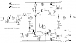
So I redesigned it with mje340 to track output baising better, no switching fets used.
Here is my version with a few improvements.
An externally hosted image should be here but it was not working when we last tested it.
Hi Nigelwright7557,
The added trim pot at the tail is handy for zeroing the output. Using mpsa92/ mpsa42 within vas stage I've not tried that yet as I use mje340 and mje350 here.
The added trim pot at the tail is handy for zeroing the output. Using mpsa92/ mpsa42 within vas stage I've not tried that yet as I use mje340 and mje350 here.
Hi Nigelwright7557,
The added trim pot at the tail is handy for zeroing the output. Using mpsa92/ mpsa42 within vas stage I've not tried that yet as I use mje340 and mje350 here.
The trim pot probably isn't required and is just another thing to go wrong but I added it in case required. It can be linked out if you don't want it.
The mpsa42/92 are just high voltage general purpose transistors that I have lots of.
With the MJE340/350 you could drive multiple pairs of output transistors.
Last edited:
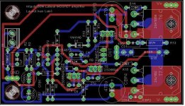
I designed double sided PCB for Hitachi app. note amp and added a few details from Maplin kit PCB, gate resistors and another 27pF cap. The PCB is star grounded and bypass caps are very close to output transistors which are TO3P packages so that the board can be piggy back mounted to the heatsink. Dimensions are 100 x 55 mm. P1 and P2 are solder pads for output coil. Feedback caps are two elcos connected in series to function as a bipolar cap.
But now I am curious to design another PCB version with ground plane on one or both sides. Any comments why that could be bad idea?
But now I am curious to design another PCB version with ground plane on one or both sides. Any comments why that could be bad idea?
Attachments
Last edited:
Looks like your signal to the speaker is being feed via that 10 ohm resistor...it should be a coil instead say 20 turns with the 10 ohm parallel to it.
Last edited:
Connect speaker return to power ground on the PCB, then connect input ground via a 10 ohm resistor to this point
10 ohm resistor is in parallel with coil. Coil is reperesented in the sch and pcb as P1 and P2 solderpads. When the coil is soldered output will go through it, not through 10 ohm resistor that is in parallel with the coil. I did not find the coil footprint in the libraries so I used solderpads. Coil will be on the top of big 10 ohm resistor. It's only not represented on the sch and pcb.
Speaker return will go to the main star ground on the chassis or to the ground plane of the PSU pcb.
Speaker return will go to the main star ground on the chassis or to the ground plane of the PSU pcb.
Last edited:
That's not ideal, this will explain the best way to do it and why https://web.archive.org/web/2017071...re-up-a-Power-Amplifier_Updated-Autosaved.pdfSpeaker return will go to the main star ground on the chassis or to the ground plane of the PSU pcb.
Speaker return will go to the main star ground on the chassis or to the ground plane of the PSU pcb.
Speaker return goes to smoothing capacitors otherwise it will modulate the ground line.
My only criticism of your circuit is I would have used a 1ma constant current source in place of R4.
Last edited:
Absolutely NOT !Speaker return goes to smoothing capacitors otherwise it will modulate the ground line.
Absolutely NOT !
Why not ?
It returns high current right back to source of power.
page 14 gives the correct location for the Speaker Return. Earlier pages give the impression that smoothing caps is the correct, but smoothing caps is wrong.That's not ideal, this will explain the best way to do it and why https://web.archive.org/web/2017071...re-up-a-Power-Amplifier_Updated-Autosaved.pdf
That way back is an old guide that has been superseded by the new guide on the still current Hifisonix website.
http://hifisonix.com/wordpress/wp-c...to-wire-up-a-Power-Amplifier-October-2017.pdf
read about charging pulses on the rectifier/smoothing capacitor circuit.Why not ?
It returns high current right back to source of power.
page 14 gives the correct location for the Speaker Return. Earlier pages give the impression that smoothing caps is the correct, but smoothing caps is wrong.
That way back is an old guide that has been superseded by the new guide on the still current Hifisonix website.
http://hifisonix.com/wordpress/wp-c...to-wire-up-a-Power-Amplifier-October-2017.pdf
But page 14 shows return path going to smoothing caps !!!!
It makes sense to go back to power source which is smoothing caps.
If you don't you will modulate the zero volt line.
Pretty much every book and website I have read says smoothing caps are best return point.
No, it does not.But page 14 shows return path going to smoothing caps !!!!
It shows a tap taken from the smoothing caps to a bus that carries a variety of tappings for various parts of the amplifier and auxilialaries.
If you look at the document I linked in post73, you will see the drawing with explanation.
You will find this has been discussed on this Forum for all the time I have been a member and still the majority get it wrong.
The charging pulses for the smoothing capacitors are what does the disturbing of the audio reference node.It makes sense to go back to power source which is smoothing caps.
If you don't you will modulate the zero volt line.
You are right in one important respect. The current that comes out of the +ve supply rail MUST RETURN to the Zero Volts node to go back through the smoothing capacitor/s to the original SOURCE.
The current returning to the -ve supply node must be sourced by the Zero Volts node.
Those Flow and Return circuits form loops and those loops MUST have low loop area to minimise interference (EMI).
if you are reading those references correctly then ALL of those references are wrong. Or you are misinterpreting what they are telling you.Pretty much every book and website I have read says smoothing caps are best return point.
Last edited:
The current returning to the -ve supply node must be sourced by the Zero Volts node..
No it doesn't.
It goes from smoothing capacitor, through amp, through speaker back to centre of smoothing caps.
Well, yes, but......conventionally we imagine it flows from positive to negative, it doesn't really matter though... 😉🙂
- Home
- Amplifiers
- Solid State
- Maplin MosFET Amplifier GA28F construction thread