Are you aware that the sensor detects only one of the magnet poles?
Also, there are different kids of sensors, mine looks just like your picture but is labeled A3144.
Eventhough I'm an electronics DIY'er and never built up anything like this in the past. I used my experience to locally source the sensor that match the specified part, it works flawlessly as I see it.
As for the magnet, I used a very ordinary coin magnet but very strong magnetism purchased from local Japanese Daiso 100Yen store. Stuck a piece under my thick VPI platter. I did some tests, no problems. Only a matter of housing all the electronics. Keep them coming, love to see ideas of you folks housing the stuff and using it. I'm intending to install this into an upcoming SG-4 speed controller.
Hi, if it´s a 3144 or some like that it will only detect one of the poles. I tested it here many times to confirm that the assembled project would work. My goal was to find the smallest possible magnet to avoid any interference with the MC cartridge and I ended up selecting a tiny cilindrical neodymium magnet, with a matchstick thickness that was very easy to attach to the platter. Of course, if you reverse both the sensor side and the magnet pole it will work too.
Hi Bill,
The hall sensor I bought claims to recognize magnetic fields and work with 4.5 to 48v. I have connected the S pin (right) to PWM3, Centre to 5v and the last to ground. The small LED does not light up when I move a magnet near it. I would have thought the LED would light if it detected a magnetic field. I have tried all the magnets I can find with no luck. I will buy a bar magnet with marked poles tomorrow to make sure. The A44E works with either poles I think. I guess I could try and find a A3144 which may take a few days. Maybe a proximity sensor as well.
Regards,
kffern
Hello kffern,
Better than try a larger magnet, try to find a 3144 sensor, they are cheap and should work as you want, the on-board led light up when it detects a signal of the correct polarity.
Good Luck!
Better than try a larger magnet, try to find a 3144 sensor, they are cheap and should work as you want, the on-board led light up when it detects a signal of the correct polarity.
Good Luck!
I can't see the traces on the PCB or which Hall device it uses, so I don't know if you have it hooked up correctly or not (or if the LED is a power indicator or output indicator). If the LED is not on the output, the PCB may need a pull up resistor on the output which can be provided by programming the Arduino pin for pull up function. You should be able to see the output change with a volt meter. The threshold is 30 gauss so it does not need a strong magnet, but it may only respond to one pole.
I have it now. It was my poor eyesight getting the earth pin wrong. I should bring my work multi focals home more often. It does only work with a south pole but that shouldn't not a problem I think. Now to box it up when I get back next week.
Thanks.
kffern
Thanks.
kffern
Hi,
For those that are looking for a bracket for the display attached it is a link for one that it is very interesting for your consideration. It come in 2 lines and 4 lines and the display it is included.
link: Blue Serial IIC/I2C/TWI 1602 16X2 Character LCD LED Display & Stand For Arduino | eBay
For those that are looking for a bracket for the display attached it is a link for one that it is very interesting for your consideration. It come in 2 lines and 4 lines and the display it is included.
link: Blue Serial IIC/I2C/TWI 1602 16X2 Character LCD LED Display & Stand For Arduino | eBay
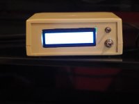
Now completely assembled into a small case, wireless, using a 9V battery and the sensor is also attached to the case.
YouTube
Very cool!
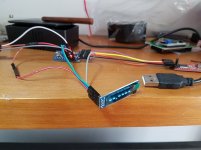
My Falcon PSU finally arrived from USA, the tachometer signal didn´t work at first attempt.
I wired the plug as instructed by Bill, shield (gnd) and ring (Rxd), no tip connection.
Maybe my TTL>RS232 labels are incorrect, because I connected the TX signal from the Arduino to the RX of the interface TTL side and then the TX of the interface RS232 side to the plug ring (Rx).
If I connect the plug ring to a DB9 #2 pin and plug shield to a DB9 #5 pin of an old computer, that should read the data from a terminal program linked to the corresponding COM port, right ???
Anyway, the RPM readings from the tachometer, just with the Falcon PSU alone, are now A LOT more stable, and can be precisely adjusted! What a great product!!!
I don´t understand the reason why the Roadrunner is completely sold out and it´s still possible to find a Falcon or Eagle PSU ?
Because, if someone choose to buy just one, a PSU unit is the obvious choice.
Last edited:
I used one of these with my RS232 shield and a radio shack mini cable, which wound up a little bulky, but *MUCH* easier: Amazon.com: DB9 Male Signals Breakout Board RX TX GND 3-Pin: Home Audio & Theater
Because many motors aren't synchronous AC motors, and thus wouldn't see much benefit (other than cleaner power). DC motor-driven decks could still use a Roadrunner, or even one of these DIY tachs, independently from the PSU.Anyway, the RPM readings from the tachometer, just with the Falcon PSU alone, are now A LOT more stable, and can be precisely adjusted! What a great product!!!
I don´t understand the reason why the Roadrunner is completely sold out and it´s still possible to find a Falcon or Eagle PSU ?
Because, if someone choose to buy just one, a PSU unit is the obvious choice.
How does Zmck's tacho reads to 4 digits? Its probably buried in the thread somewhere? 3 is plenty for my TTs though.
I am using a proximity sensor and it works well. Its surprising how long my Lenco takes to settle down to a steady speed. Using my Lenco Heaven PS its difficult to set an accurate speed. Now to start on Pyramids PS.
Regards,
kffern
I am using a proximity sensor and it works well. Its surprising how long my Lenco takes to settle down to a steady speed. Using my Lenco Heaven PS its difficult to set an accurate speed. Now to start on Pyramids PS.
Regards,
kffern
Last edited:
How does Zmck's tacho reads to 4 digits? Its probably buried in the thread somewhere? 3 is plenty for my TTs though.
I am using a proximity sensor and it works well. Its surprising how long my Lenco takes to settle down to a steady speed. Using my Lenco Heaven PS its difficult to set an accurate speed. Now to start on Pyramids PS.
Regards,
kffern
It has to do with the last parameter in the line that sends the reading to the LCD: LCD.print(RPM,3);
In my code, I set the decimal parameter to 3 because of the sampling frequency I used (31.25kHz). A count of 56250 would yield 33.3333333 RPM and a count of 56251 (+1) would yield 33.33274, so the effective resolution is only 3 decimal places.
On some of the earlier code scripts, the sampling frequency was 250kHz which would allow higher resolution than 3 decimal digits, but in practice, trigger ambiguity and other tolerances effectively makes anything more than 3 decimal places moot.
That being said, you can display as many decimal places as the Arduino function can return.
Sorry, I forgot to explain about the four decimal digits "precision"...
When testing the OLED display I wanted to know the maximum number of large digits possible to show and ended up with 4. So, it has nothing to do with an enhanced resolution.
I will reduce to 3 digits when I assemble it in a definitive aluminum case to pair with the Falcon.
When testing the OLED display I wanted to know the maximum number of large digits possible to show and ended up with 4. So, it has nothing to do with an enhanced resolution.
I will reduce to 3 digits when I assemble it in a definitive aluminum case to pair with the Falcon.
I would also recommend adding some damping material between the case and plinth *IF* you plan to leave your tach on the plinth during playback, is it would introduce some weird resonance back into your plinth. If it's just for setup, and removed during playback, no worries. 😛I will reduce to 3 digits when I assemble it in a definitive aluminum case to pair with the Falcon.
Sure, that portable 9v battery operated version I made for tests and to be used just as a tool for quick setup of friends turntables.
The definitive version will have a case similar to the Falcon PSU and will be placed under the TT.
I´ve just ordered the aluminum case from this website:
MWF eStore
It will be precisely CNC machined to fit the OLED display at the front panel and the connectors on the rear.
The definitive version will have a case similar to the Falcon PSU and will be placed under the TT.
I´ve just ordered the aluminum case from this website:
MWF eStore
It will be precisely CNC machined to fit the OLED display at the front panel and the connectors on the rear.
I thought I would post pictures of my implementation. Thanks again Pyramid, Tauro and all those who assisted getting this done for us.
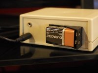
I have 2 inputs at the back which are switched from the upper toggle switch on the front panel. The battery at the back is for when I move it to the other system. I use a wired snap on 9v connector wired to a female DC plug to go to a 9V plugback for normal use. I use a proximity sensor with a 3.5mm stereo plug.
The arduino clone, display and sensor cost me AUD30 The box and plugs another $20 or so.
Sorry about the display but it got lost in the glare. The display cutout was a bit of a hatchet job.
I can post links to the parts I bought to help Aussie builders if any one is interested.
Regards,
kffern
Attachments
Last edited:
- Home
- Source & Line
- Analogue Source
- Digital Tachometer for record player (LCD display)