Why did you change your mind?
I recently heard the pre65 amps at a DIY event in England driving a pair of open baffles. They sounded fine though it was difficult to tell much given the acoustics of a large reception sized room with unforgiving speaker placement. The heat sinks measure 13" x 8" x 3" and barely get warm when the fan is running.
There are photos at Ray's Retirement: Owston - a visit to DIY Audio Land
The amp sounded good enough to persuade me to build a pair when I get back to the US. I have enough heat sinks and I am going to go the SMPS route. I had wondered about doing a 48 volt version but after discussion with pre65 I will go with 60 volts. Hopefully my Mouser order will be waiting for me at home and I will get them done before September when I head off to Oz.
ray
Shade 50 in action

Interesting blog thank you

ps: i like it that photography's
Attachments

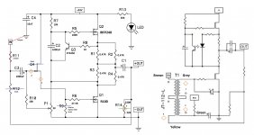
Here is a scaled down version of the 50w Schade circuit. I built it into a pair of ACA chassis using the ACA boards and a Semisouth R100 for Q1. It runs about 1.2A bias at 24V. I don't have a distortion analyzer so I cant provide those numbers, but it does sound nice.
The ACA circuit and board must be modified by omitting Q4, R9, R12, and R15. Jumpers must be installed across R11 and from In to Ground. R14 must be replaced by the two feedback resistors standing vertically off the board.
The ACA circuit and board must be modified by omitting Q4, R9, R12, and R15. Jumpers must be installed across R11 and from In to Ground. R14 must be replaced by the two feedback resistors standing vertically off the board.
Attachments

Super! 🙂
@ Michael R
Any posibility for Diyers who don't practice point-to-point amplifier construction
to buy your design 2 pcb's Schade50W set in AudioMaker.tech shop ?
Buy Stuff | AudioMaker
Maybe try made pcb's small run for interested guys ?
Kindest regards
My intention was to do some boards, test them, and give them to the guys at diyAudio to use as they see fit. But, it appears that for the general DIYer, an input buffer is going to be practically mandatory and I have yet to go back and add a buffer to my boards. This is still on my to-do list, but presently my day job (we acquired another company so now I have two day jobs) is limiting my bandwidth. 🙂
It will likely be later this Fall before I get to it, and I wouldn't be the least bit offended if someone beats me to it. I'm sorry, I haven't been as productive this year as I would like. 🙂
It will likely be later this Fall before I get to it, and I wouldn't be the least bit offended if someone beats me to it. I'm sorry, I haven't been as productive this year as I would like. 🙂
Last edited:
An input buffer in front of the Jensen.
Lot's of cap-coupled preamps out there, and a I thought a built-in buffer would make it more fool-proof for the beginner/general builder. 🙂
Lot's of cap-coupled preamps out there, and a I thought a built-in buffer would make it more fool-proof for the beginner/general builder. 🙂
Mr Pass suggested a resistor to ground on input.
Highlighted it in post 1. Nice to know we have options. 🙂
Highlighted it in post 1. Nice to know we have options. 🙂
Yes, the buffer solves a couple of problems for beginners, who might not be aware their spiffy tube preamp is cap-coupled and has a 2K ohm output impedance.
Of course, experienced FABs can bypass all this. 🙂
Perhaps this is belt and suspenders on my part. I defer to the wisdom of the group.
Of course, experienced FABs can bypass all this. 🙂
Perhaps this is belt and suspenders on my part. I defer to the wisdom of the group.
Take it you didn't use the opto-coupler?
Did you have to change R1 & 3?
Nope, no opto-coupler. The ACA circuit does the same basic thing though.
Didn't have to change any of R1-4. In fact I built it with the standard ACA values there first. Sounded fine. I only changed them to bump up the bias a bit without resorting to R15 and to tap the actual midpoint.
The circuit is quite flexible and will work nicely with many options for Q1 that can plug right in. IRFP240 included. For those who want more power the ACA board should bolt right into the larger deluxe chassis in the store. That would allow much more voltage and bias.
My intention was to do some boards, test them, and give them to the guys at diyAudio to use as they see fit. But, it appears that for the general DIYer, an input buffer is going to be practically mandatory and I have yet to go back and add a buffer to my boards. This is still on my to-do list, but presently my day job (we acquired another company so now I have two day jobs) is limiting my bandwidth. 🙂
It will likely be later this Fall before I get to it, and I wouldn't be the least bit offended if someone beats me to it. I'm sorry, I haven't been as productive this year as I would like. 🙂
Busy modern life !
All major time at work or two jobs 😀
Find moments for family and friends and
if miracle happen for diyAudio hobby as well.
Buffered Schade50W version pcb's boards is a genious great idea !
Thanks Michael for sharing of your precious time on the forum with us.
Attachments
Nothing new on my part. I was just going to lift Nelson's complementary JFET buffer and put it in there. 🙂
I'm interested in the opinion of the group though. Is it overkill?
I'm interested in the opinion of the group though. Is it overkill?
I don't think so. Could use something like B1 v2 or something like what you did with the Luminaria (sp?).
...... I was just going to lift Nelson's complementary JFET buffer and put it in there. 🙂
......
...... Could use something like B1 v2 .......
that's the same thing
- Home
- Amplifiers
- Pass Labs
- 50w Single-Ended BAF2015 Schade Enabled