yup , counting on
Thanks Mighty !
Look Yamaha produce special ZM tribute 2SK77 😀
Attachments

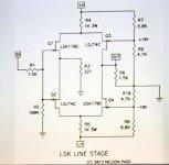
Optimised LSK line stage schematic version for Schade 50W request 🙂
2013 Burning Amp Speaker: Nelson Pass - YouTube
Haha that make me optimistic and watch Master video about excellent LSK line stage.
IXYS hockey puck transistor one hand clap give 20 dB of gain alone.
LSK is resisitive coupled without cap on original schematic.
Logicaly no more motor boat noise.
Second harmonic sound character who match perfectly with amplifier as well.
Possible implementation of small potentiometer, trimmer into circuits
if Diyers want get play with third and second charmonics sound to yours taste.
20 Ohm output impedance preserve wideband frequency response to enjoy music with yours amazing super tweeters.
Please can i request optimised schematic of LSK for Schade 50 with adapted gain,appriopriate jfets Idss grade ,
output impedance, volume pot, sources switch, and psu voltage for that purpose ?
Greetings 🙂
Attachments
Thanks Mighty !
Look Yamaha produce special ZM tribute 2SK77 😀
send them to OPLDF

That sounds like an RFQ. 🙂
Any constructive answers are welcome

send them to OPLDF
Yup i get mysterious stuff to send to mysterious place and please keep all that secret with me

UFO semi's is logicaly destinated only to Alien Laboratory.
Photos was 🤐 by the NASA agency 😉
My apologies for all terrestian's 😀
Attachments


That will do it. If your supply is quiet, you can also do D-S
on the current source (gives more bias instead of subtracting
some bias).
Thank you.
Have not experienced any tendency towards motorboating after installation of the 220 Ohm resistor
I've got some distortion numbers now for the scaled down Schade circuit with SS R100s from post #422. (Thank You Mr. Rothacher!)
At 24V and 1.2A bias I'm seeing:
0.53% at 1W into 8R and 1kHz.
0.69% at 1W into 8R and 20kHz.
2.0% at 1kHz into 8R occurs at 5.4W
I'm not sure about the output impedance or the open loop gain of the circuit. It sounds very nice with the current 20dB of gain, and has bandwidth with a 50R source out well past 40kHz. I am curious to know how it would perform with less gain/ more feedback. At this point I think doubling the bias and heatsinking would be the most fun.
The distortion seems high, doesn't it?
Yes it does. So i went back to #422 with the modified ACA schematic.
It looks to me as being neither ACA nor Schade feedback amp. The connection of the feedback resistors differs from the original..?😕
The distortion numbers are similar to the ACA, and actually a bit better at high frequencies. I was expecting slightly better numbers, but those might only be attainable with higher bias or more feedback?The distortion seems high, doesn't it?
The only differences from the Schade circuit are the transistors, the use of an ACA current source (no optocoupler), and the voltage/current (24V/1.2A).It looks to me as being neither ACA nor Schade feedback amp. The connection of the feedback resistors differs from the original..?
Nope. That would be true if R12 was not omitted though.In schematic #422 the OUT+ is directly connected to C3 and C4
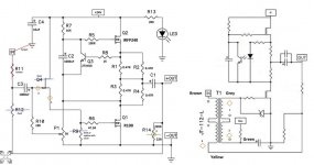
Here is the schematic with vestigial traces removed for a bit more clarity.
I think the gain is too high currently and the feedback network doesn't get enough bite into the OLG to work as well as it could. I'll tinker with it and probably set it to about 14dB like the ACA then test it.
Attachments
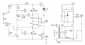
Ok, with feedback resistors set at 220R/37R4 the distortion is 0.42% at 1W/8R/1kHz and 0.55% 1W/8R/20kHz. Now it does 6W at 2% and 1kHz.
Ok. I can see clearly now (doesn't happen every day)
Only "schade" (in German "schade" means "a pity") that the distortion figures are not lower.
How did you get those?
Only "schade" (in German "schade" means "a pity") that the distortion figures are not lower.
How did you get those?
Michel Rothacher got 0.04% THD for 1W out of the original circuit (#857 BAF2015 coverage)
Of course this is for different components at different conditions. Nevertheless the difference is very big.
Of course this is for different components at different conditions. Nevertheless the difference is very big.
I've got a noisy smps. By moving it as far away as possible the distortion has dropped to 0.21%. I'm going to try to find a quieter supply and test some more.

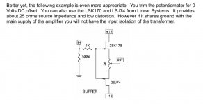
Ok thx the impedance buffer for Schade50 optimal frequency bandwith response is the one from CSX1 article.
IXYS and his 20dB is my candidate to use with passive LDR or AVC volume controls.
Schematic courtesy of First Watt Saint Patron

Attachments
Papa say on video BAF " is worst the efforts "
that mean for me little efforts
if compare to joy of use such single-ended giant amp 😉
Have fun


Typo correction " It's worth the efforts "
Best regards
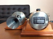
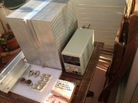
Nice heatsink you got there
Metal drill work on heat sink's is now ready and I completed all components exception small bias psu.
Let's run hot IXYS hockey pucks

- Home
- Amplifiers
- Pass Labs
- 50w Single-Ended BAF2015 Schade Enabled