Hi Shaan
I will build another V1.. but i have some mje’s in my drawer.. and i plan to use them instead of bd’s if it possible.
Should I pay attention with another parts concerning to this replacement. Thank You
Best Regards
I will build another V1.. but i have some mje’s in my drawer.. and i plan to use them instead of bd’s if it possible.
Should I pay attention with another parts concerning to this replacement. Thank You
Best Regards
Hi Shaan
I will build another V1.. but i have some mje’s in my drawer.. and i plan to use them instead of bd’s if it possible.
Should I pay attention with another parts concerning to this replacement. Thank You
Best Regards
You are okay to go with MJEs without any change in the other components. Instead of V1, go for V1.1; it's much better.

You are okay to go with MJEs without any change in the other components. Instead of V1, go for V1.1; it's much better.
Ok .. my mistake .. I mean V1.1..
thank you so much
Best Regards
I am sorry, I think I miss something. How to measure bias on V1.1 and preferable mA ..You are okay to go with MJEs without any change in the other components. Instead of V1, go for V1.1; it's much better.
thank you.
Best regards
I am sorry, I think I miss something. How to measure bias on V1.1 and preferable mA ..
thank you.
Best regards
VAS bias is measured around any of the two 10R resistors closest to VAS transistors. Set multimeter to "mV" and measure the voltage around one of these resistors. Divide that reading by 10 and you get VAS bias in mA.
10mA is a good bias. So you would want to get a reading of 100mV around each 10R VAS resistor. Turn the trimmers slowly in small steps for that. If turning one of them seems to increase or decrease the VAS bias too far from 10ma (i.e. 100mV) then leave that trimmer and turn the other one.
MOSFET bias is auto-set by the two 1N4148 diodes between 150mA and 200mA.
Hi shaan,
Would you be considering v2 version of v4 anytime
Also any recommendation on power supply
Thanks
Ajit
Would you be considering v2 version of v4 anytime
Also any recommendation on power supply
Thanks
Ajit
Hi shaan,
Would you be considering v2 version of v4 anytime
Also any recommendation on power supply
Thanks
Ajit
Hi Ajit.
Currently no plan for a high power version.
You can use any basic dual rail PSU with V4 as well as more sophisticated ones. A bank of minimum 20,000uF per channel is recommended.
A suitable PSU PCB for all peeceebees including V4 is under development. Will be available next month if everything works as expected. 🙂
Thanks Shaan, looking forward to the power supply, great to know it would be flexible enough for both dual mosfet/regular versions.
Hello guys.
Here are the schematics for the V1.1 and the new V2 layouts. (sorry for the delay 😱 )
Thanks to everyone for making the PeeCeeBee thread what it is.
Also thanks admin for the warning. Disaster avoided! 😀
shaan
Hi Shaan,
For the V2 build with +/- 48 to 50 VDC,
I have
1. for the 1000uF - I have 220uF 63V
2. for 2200uF - I have 2200uF 25V
3. for 470uF - I have 220uF 63V
I am guessing (value-wise and voltage-wise), these should be ok, but would like to have your opinions.
reg
Prasi
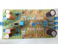
Here is my V2 build.
used nichicon 220uF 63V for rail decoupling
i/p decoupling, used nichicon gold kz 220uF 63V
and for feedback, used keltron 2200 uf 16V.
funny, esr was lowest for keltron😕 and value was very very close to the nominal value🙂..
just finished soldering , yet to clean the bottom😱. I hope I dont run into problems. fingers crossed for testing.
Attachments
Nice!Here is my V2 build.
used nichicon 220uF 63V for rail decoupling
i/p decoupling, used nichicon gold kz 220uF 63V
and for feedback, used keltron 2200 uf 16V.
funny, esr was lowest for keltron😕 and value was very very close to the nominal value🙂..
just finished soldering , yet to clean the bottom😱. I hope I dont run into problems. fingers crossed for testing.
What is the code for these insulated fastons?
Are they pressed together with the insulation material or without them?
ok here are the test results.
offset 1.2 mV
I used a 10 R rail res on V+ to measure total bias.
The del V across 10 R rail res is 369mV.
giving a total bias current of 39mA.
is it correct? Appreciate it if any of the builder helps, I guess Shaan is not available at the moment.
offset 1.2 mV
I used a 10 R rail res on V+ to measure total bias.
The del V across 10 R rail res is 369mV.
giving a total bias current of 39mA.
is it correct? Appreciate it if any of the builder helps, I guess Shaan is not available at the moment.
Nice!
What is the code for these insulated fastons?
Are they pressed together with the insulation material or without them?
male part TE connectivity 1742686-1
female part TE connectivity 3-520406-2
very nice quality and perfect. male part has stability protrusions at bottom ( see the curved protrusions at pcb mounting surface). aliexpress stuff is filthy and flimsy.
if you have nice Stanley crimp tool, you are good to go with any amp build that uses fastons. just buy it blindly.
the female part comes with faston receptacle with insulation. insulation part is detachable but with some difficulty.
so very safe.
Prasi,
Maybe this will help.
Hi Rick,
thanks for sharing.
I built PEECEEBEE V1 using same guidelines.
and same used for v2build.
I would like to know whether the bias is ok for v2. seems much much less as compared to V1.😕
I thought lats have optimum bias at 160 mA. VSSA, PEECEEBEE and Apex FX-8 that i built used about 130 -200 mA.
here are the measurements.
Iq- 36.8 mA
Front end + VAS- 5.8mA
thro VAS emitter resistor - 2.7mA
o/p bias - 31mA
SOunds good , very neutral and not harsh or subdued.
managed to put it in a DIY case and will serve as a sub amp.
Iq- 36.8 mA
Front end + VAS- 5.8mA
thro VAS emitter resistor - 2.7mA
o/p bias - 31mA
SOunds good , very neutral and not harsh or subdued.
managed to put it in a DIY case and will serve as a sub amp.
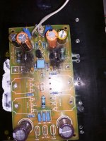
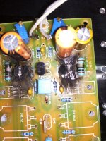
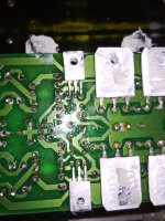
the joy was somewhat short lived.
while listening music, there was some sound and fire😀. I immediately hit the main switch.
bad resistors that shorted?😕
or problem with MJE's?
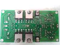
bottom side is quite fine.
same pattern of burning on both sides!!
while listening music, there was some sound and fire😀. I immediately hit the main switch.
bad resistors that shorted?😕
or problem with MJE's?
bottom side is quite fine.
same pattern of burning on both sides!!
Attachments
O Prasi,i'm sure it's a transistor fail.
I have used KSC3503,A1381 for vas in this amplifier,these aren't on main heatsink in my case but small heatsinks are attached to each of them.
I have used KSC3503,A1381 for vas in this amplifier,these aren't on main heatsink in my case but small heatsinks are attached to each of them.
Last edited:

- Home
- Amplifiers
- Solid State
- PeeCeeBee