You are welcome.
Have you got the V3 PCBs? If yes then take pix fast and show us. 🙂
I didn't get my V3 yet... the package is in Canada already.
Hi Shaan! What type of capacitors for Peeceebee? Panasonic FC ? Panasonic FM ?
And what Polypropylene?
And what Polypropylene?
I didn't get any noticeable difference in terms of sonic quality with Panasonic FC in V3 in comparison to local indian capacitors.Hi Shaan! What type of capacitors for Peeceebee? Panasonic FC ? Panasonic FM ?
And what Polypropylene?
But for longer life and consistency I would go for Panasonic FC again as FM series are hard to find here.
Sent from my GT-N7100 using Tapatalk
For V4 I would also like to use vishay dale Rn55d or Rn60d to see I'd there's any difference. If not, again the long life and consistency will be ensured. [emoji12]I didn't get any noticeable difference in terms of sonic quality with Panasonic FC in V3 in comparison to local indian capacitors.
But for longer life and consistency I would go for Panasonic FC again as FM series are hard to find here.
Sent from my GT-N7100 using Tapatalk
Sent from my GT-N7100 using Tapatalk
In for V4 GB. However. I already have some PSUs laying around. Is +-45Vdc doable if some parts are changed?
Sincerely
Sincerely
Hi Shaan! What type of capacitors for Peeceebee? Panasonic FC ? Panasonic FM ?
And what Polypropylene?
NICHICON FINE GOLD!!!!!!!!!

Sorry I can't find any here and so that happened. 😀😛
On a serious note, if the capacitors aren't fake then any will work well. Panasonic will work fine with Wima redboxes. I use Keltron for the supply bypass eletros, Nippon Chemi-con for feedback electros, Epcos for all the 100nF+1uF and GMEL for 100pF and 47pF ceramics.
All electrolytics are 5mm pin pitch. All film-types are 5mm pin pitch. The two 47pF are 5mm or 7.5 pin pitch (there will be pads for both type). The 100pF is 7.5mm pin pitch.
In for V4 GB. However. I already have some PSUs laying around. Is +-45Vdc doable if some parts are changed?
Sincerely
+/-45V is doable with MJE for q9/q10 and BC546/556B for all small trannies. Load impedance must not be less than 8ohm.
mmmmm..... the best Nichicon i can find are the KZ series on Banzaimusic in Germany.
Another thing: for the ver 1.1, what type and value of fuse must use?
And what type of heatsink? And very last and important thing: I have buyed a secondhand Talema toroidal 25+25 6A tot. As more pepople, it have a little hum, so I need a DC trap. have you tried some? can somebody help me?
Another thing: for the ver 1.1, what type and value of fuse must use?
And what type of heatsink? And very last and important thing: I have buyed a secondhand Talema toroidal 25+25 6A tot. As more pepople, it have a little hum, so I need a DC trap. have you tried some? can somebody help me?
Audiophonics.frmmmmm..... the best Nichicon i can find are the KZ series on Banzaimusic in Germany.
Another thing: for the ver 1.1, what type and value of fuse must use?
And what type of heatsink? And very last and important thing: I have buyed a secondhand Talema toroidal 25+25 6A tot. As more pepople, it have a little hum, so I need a DC trap. have you tried some? can somebody help me?
thank you shaan for the answer to my previous question. easy to understand. 🙂
please tell me, does the lower gain of this amp increase the stability? i drive horn speakers with vssa and would like to lower the overall gain, to say x5 or even less.
would be nice if i could use peeceebee as a buffer type, like pass F4, and fiddle with the preamp more. 🙂
please tell me, does the lower gain of this amp increase the stability? i drive horn speakers with vssa and would like to lower the overall gain, to say x5 or even less.
would be nice if i could use peeceebee as a buffer type, like pass F4, and fiddle with the preamp more. 🙂
thank you shaan for the answer to my previous question. easy to understand. 🙂
please tell me, does the lower gain of this amp increase the stability? i drive horn speakers with vssa and would like to lower the overall gain, to say x5 or even less.
would be nice if i could use peeceebee as a buffer type, like pass F4, and fiddle with the preamp more. 🙂
Hello donovas. My pleasure.
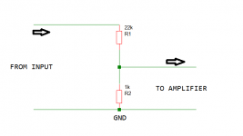
Lower gain in this amp will decrease stability. If you want lower effective gain from the amplifier then I would suggest you keep the amplifier's internal gain at default 23 and use a resistive divider with 22k+1k at the input. This configuration will make the amplifier behave like a unity gain follower.
Procedure: Join one end of both resistors to each other. Connect the external input signal wire to the open end of 22k. Connect the amplifier input to the two resistors' joint. Connect the 1k resistor's open end to ground.
See attachment for illustration.
🙂
Attachments
Hello Guys.
I finally got my V3 pcbs. however I made one mistake and i got 1N4148 of 150ma instead of 200ma so I had a bad 2nd order distortion. I guess 200ma is the sweet spot for the lat mosfets.
So my question can I replace the 1N4148 diodes by a trimmer? and test different mosfets biasing?
Thanks
I finally got my V3 pcbs. however I made one mistake and i got 1N4148 of 150ma instead of 200ma so I had a bad 2nd order distortion. I guess 200ma is the sweet spot for the lat mosfets.
So my question can I replace the 1N4148 diodes by a trimmer? and test different mosfets biasing?
Thanks
Hello Guys.
I finally got my V3 pcbs. however I made one mistake and i got 1N4148 of 150ma instead of 200ma so I had a bad 2nd order distortion. I guess 200ma is the sweet spot for the lat mosfets.
So my question can I replace the 1N4148 diodes by a trimmer? and test different mosfets biasing?
Thanks
Congrats on having them finally!

Did you trim the offset? What is VAS bias? Show pictures if possible, a lot of pictures!
Congrats on having them finally!
Did you trim the offset? What is VAS bias? Show pictures if possible, a lot of pictures!
Hello Shaan.
this problematic V3 has the bds not matched at all.. so I tried an input with a trimmer to try to offset the lacking of matching. so far it failed to provide a good distortion profile. tomorrow I will receive more bds I might have a good match. So as soon as I have a well matched V3 with the correct bias. I will post pics here and the results .
Thanks.
Hi.
Did you try the onboard trimmers to trim the offset? The input should always be referenced to ground. The onboard trimmers work closer to the BDs and will show much better control over the offset than a trimmer at the input. But yes a very high hFE difference in the transistors can cause both technique to fail to do so effectively.
Will wait for your update.
Hello , I got my v3 working.
BC560C, BC560C => 629 , 627.
bd139 , bd140 => 189, 217 ( I have a better match now.. I might replace it ).
vas bias ~20ma ( I think I need to decrease it to 10ma )
mosfet bias ~100ma
thd results at 5vpp on 4ohms ==> 0.0041%
imd distortion 6.5khz , 7khz ==> 0.02%
the results are very good.
however if I increase the mosfet bias to 200ma I will might get better results.
Anybody has I suggestion on the best way to increase the bias?
right now on v3 it uses diodes and I got the 200ma ones. but the bias increases with the voltage my tests are using +\- 30v.
My guess is the majority of V3 uses +\- 35v so probably the diode goes to 200ma in my case it doesn't.
thanks
Last edited:
Hello , I got my v3 working.
BC560C, BC560C => 629 , 627.
bd139 , bd140 => 189, 217 ( I have a better match now.. I might replace it ).
vas bias ~20ma ( I think I need to decrease it to 10ma )
mosfet bias ~100ma
thd results at 5vpp on 4ohms ==> 0.0041%
imd distortion 6.5khz , 7khz ==> 0.02%
the results are very good.
however if I increase the mosfet bias to 200ma I will might get better results.
Anybody has I suggestion on the best way to increase the bias?
right now on v3 it uses diodes and I got the 200ma ones. but the bias increases with the voltage my tests are using +\- 30v.
My guess is the majority of V3 uses +\- 35v so probably the diode goes to 200ma in my case it doesn't.
thanks
Hey congrats! 🙂
To change mosfet bias remove any one of the two 1N4148 diodes and place a 500R multiturn trimmer in its place with the middle pin bent and soldered to any one of the other two pins.
Important: before soldering it to the diode's place turn it to zero resistance. With zero resistance trimmer and one diode on the board, MOSFET bias will be in the 20-30mA zone. You may want to measure its THD performance at this low bias config. Turn the trimmer to higher resistance and you will be able to increase MOSFET bias to 500mA-700mA or maybe a little higher.
Very important: MOSFET's bias with turning of the trimmer will now directly depend on VAS bias, i.e. an increase in VAS bias will now directly increase MOSFET bias even without turning the bias trimmer. Decreasing VAS bias to 10mA before increasing trimmer resistance from zero will be the wise thing to do. Also, with trimmer biasing total MOSFET bias will become much more sensitive to power supply variation. This is why the two diodes are used to auto bias the MOSFETs and keep the bias variation to minimum.
All the bests with the experiments!
Thanks for the tips.
My goal is to have the lowest IMD possible. my next step will be replace the bds by better matched ones.
what temperature on the heatsink of the bd is considered healthy ? mine is getting to 40c ( 20c above the room temperature ). looks too high. it might to much specially after I put the v3 inside a chassis, the temp will go higher for sure.
Thanks
deltaT of 20C degrees is low.
40degrees C is only slightly above your blood temperature.
No concerns.
Try to keep Tj well below 100degrees C
This might require Tc<90degrees C. That would require DeltaT of < 60C degrees when Ta = 30degrees C
Can you see that your DeltaT of 20C is way below a worst case target of DeltaT < 60Cdegrees?
Note the difference between C degrees and degrees C
A temperature measured with a thermometer is in units of degreesC
A temperature difference (DeltaT) between two bodies/states is in units of C degrees
Last edited:
- Home
- Amplifiers
- Solid State
- PeeCeeBee