Hi Chris,
I historically use NI Multisim - got lots of developments, many live-tested "building blocks", etc. From time to time live prototypes require some fine-tuning, however my simulations work rather close to reality - that's why in some cases I take the liberty to publish new circuits before they are live-tested - Jeff Wilhelm, Thimios or Terry can handle that fine-tuning nicely. My lab is "disassembled" for some time, however I plan to re-build it in mid-June - then I will publish all the measurements and test results, as I did before.
Right now I rely on DIY mates for that and very much appreciate their help
Cheers,
Valery
Compatibility
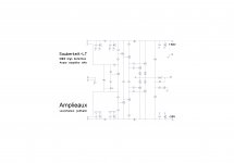
By the way, Sauberkeit-LT's IPS module shows very good results with Lichtstark-X's OPS (HexFET-based), as well as vice versa - those boards are fully compatible for being used in different combinations 😉
By the way, Sauberkeit-LT's IPS module shows very good results with Lichtstark-X's OPS (HexFET-based), as well as vice versa - those boards are fully compatible for being used in different combinations 😉
Thank you Valery and Jeff,Thank you all who trust me.🙂Hi Chris,
I historically use NI Multisim - got lots of developments, many live-tested "building blocks", etc. From time to time live prototypes require some fine-tuning, however my simulations work rather close to reality - that's why in some cases I take the liberty to publish new circuits before they are live-tested - Jeff Wilhelm, Thimios or Terry can handle that fine-tuning nicely. My lab is "disassembled" for some time, however I plan to re-build it in mid-June - then I will publish all the measurements and test results, as I did before.
Right now I rely on DIY mates for that and very much appreciate their help
Cheers,
Valery
I must prepare my <<test bed>>
Last edited:
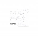
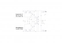
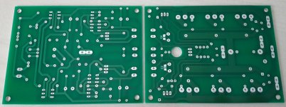
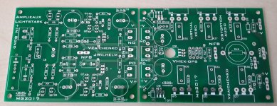
Some tryout on Valery Sauberkeit line. I try to do it the more versatil i could for OPS as you can use either 1 pair Sanken MT200, nor 1 ou 2 pairs MJL (3281/1302 or 4381/4302). Both OPS and IPS have same size : 100x76mm, same as Lichstark-IPS and VHex-OPS
Marc
Marc
Attachments

To continue....
When digital things become alive....
Related to post : http://www.diyaudio.com/forums/solid-state/277087-revisiting-some-old-ideas-1970s-ips-ops-204.html#post5066318.
Marc
When digital things become alive....
Related to post : http://www.diyaudio.com/forums/solid-state/277087-revisiting-some-old-ideas-1970s-ips-ops-204.html#post5066318.
Marc
Attachments
Good!When digital things become alive....
Related to post : http://www.diyaudio.com/forums/solid-state/277087-revisiting-some-old-ideas-1970s-ips-ops-204.html#post5066318.
Marc
I 'm waiting some new IPS for test with the NS modular OPS.
I don't know if LIGHTSTARK is one of them.
Good!
I 'm waiting some new IPS for test with the NS modular OPS.
I don't know if LIGHTSTARK is one of them.
Lichtstark is one of the input boards. They will hopefully be in the mail later today. Do you need parts for the boards?
Good!
I 'm waiting some new IPS for test with the NS modular OPS.
I don't know if LIGHTSTARK is one of them.
Hi thimios,
fortunatly, these board are not compatible with NS-Modular, i wanted something more simple even if i have NS board. These latest range of board has the same size : 100x76mm so even something more compact than NS-Modular.
Marc
I have a question about the Lichtstark IPS, for what the transistors Q3, Q7, Q9 and Q10 are used for:
http://www.diyaudio.com/forums/soli...eas-1970s-ips-ops-204.html#post5066318http://
http://www.diyaudio.com/forums/soli...eas-1970s-ips-ops-204.html#post5066318http://
I have a question about the Lichtstark IPS, for what the transistors Q3, Q7, Q9 and Q10 are used for:
http://www.diyaudio.com/forums/soli...eas-1970s-ips-ops-204.html#post5066318http://
Those transistors, together with D3, D4, D7 diodes, form a high-precision cascoded current mirror with gain, playing a role of one half of the current-driven VAS.
Last edited:
Hello,
can you explain this configuration more precise:
I recognized that Q1 and Q5 are forming a difference amplifier. But wich transistors are forming the current mirror and the cascode. So far I know a current mirror consits of to transistors with Basis Emitter in parallel and a cascode are two transistors one above the other with basis of the top transistor on ground.
can you explain this configuration more precise:
Those transistors, together with D3, D4, D7 diodes, form a high-precision cascoded current mirror with gain, playing a role of one half of the current-driven VAS.
I recognized that Q1 and Q5 are forming a difference amplifier. But wich transistors are forming the current mirror and the cascode. So far I know a current mirror consits of to transistors with Basis Emitter in parallel and a cascode are two transistors one above the other with basis of the top transistor on ground.
Hello,
can you explain this configuration more precise:
I recognized that Q1 and Q5 are forming a difference amplifier. But wich transistors are forming the current mirror and the cascode. So far I know a current mirror consits of to transistors with Basis Emitter in parallel and a cascode are two transistors one above the other with basis of the top transistor on ground.
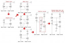
You mentioned the simplest implementations of the current mirror and the cascode.
OK - I have tried to illustrate the evolution of the current mirror in this design.
A few hints for better understanding:
- different values of the resistors in the mirror -> mirror with gain;
- transistor with the base and collector shorted can be replaced with a diode in certain conditions;
- my implementation of Hawksford cascode improves precision (the base of the cascode not necessarily has to be connected to ground, although it's still a common base circuit);
- D4 in the final schematic is level shifter; all the other diodes are parts of the Wilson mirror.
Cheers,
Valery
Attachments
You mentioned the simplest implementations of the current mirror and the cascode.
OK - I have tried to illustrate the evolution of the current mirror in this design.
A few hints for better understanding:
- different values of the resistors in the mirror -> mirror with gain;
- transistor with the base and collector shorted can be replaced with a diode in certain conditions;
- my implementation of Hawksford cascode improves precision (the base of the cascode not necessarily has to be connected to ground, although it's still a common base circuit);
- D4 in the final schematic is level shifter; all the other diodes are parts of the Wilson mirror.
Cheers,
Valery
Yes Valery and it can also be proved in performance in LTSpice simulator.
Really great work. Simple and Performe Great!
Lichtstark-X live testing - initial observations
Marc and all,
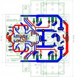
With reference to post#2039 IPS board schematic:
Lichtstark-X layouts designed by Marc
Based on live tests, performed by Jeff, with +/-48V rails, for having 6.9mA VAS idle current, R12 and R13 have to be 13K each.
Adjusting those values, you can adjust the VAS current - slightly higher values will result in lower VAS current and vice versa.
You can test IPS board standalone, connecting PD+ and ND- with 2 x 100R resistors in series, connecting NFB to their middle point and using it as output.
Check the VAS idle current by measuring the voltage drop over those resistors.
Jeff is assembling the OPS section of the amplifier, so expect some real test results pretty soon 😉
Cheers,
Valery
Marc and all,
With reference to post#2039 IPS board schematic:
Lichtstark-X layouts designed by Marc
Based on live tests, performed by Jeff, with +/-48V rails, for having 6.9mA VAS idle current, R12 and R13 have to be 13K each.
Adjusting those values, you can adjust the VAS current - slightly higher values will result in lower VAS current and vice versa.
You can test IPS board standalone, connecting PD+ and ND- with 2 x 100R resistors in series, connecting NFB to their middle point and using it as output.
Check the VAS idle current by measuring the voltage drop over those resistors.
Jeff is assembling the OPS section of the amplifier, so expect some real test results pretty soon 😉
Cheers,
Valery
Yes Valery and it can also be proved in performance in LTSpice simulator.
Really great work. Simple and Performe Great!
Thank you Ronaldo 😀
You mentioned the simplest implementations of the current mirror and the cascode.
OK - I have tried to illustrate the evolution of the current mirror in this design.
A few hints for better understanding:
- different values of the resistors in the mirror -> mirror with gain;
- transistor with the base and collector shorted can be replaced with a diode in certain conditions;
- my implementation of Hawksford cascode improves precision (the base of the cascode not necessarily has to be connected to ground, although it's still a common base circuit);
- D4 in the final schematic is level shifter; all the other diodes are parts of the Wilson mirror.
Cheers,
Valery
Hi Valery,
thank you for the explainations with graphics - it will help me to understand the schematic 😉.
Hi Valery,
thank you for the explainations with graphics - it will help me to understand the schematic 😉.
You are welcome 😀
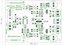
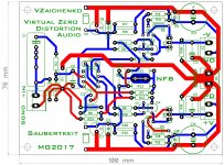
Some revision on Saubertkeit OPS....something more universal as it can use ON semi NJW or MJL and even 2 pairs sanken MT200 in small form factory as 100x76mm....
Attachments
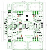
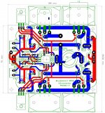
Some revision on Saubertkeit OPS....something more universal as it can use ON semi NJW or MJL and even 2 pairs sanken MT200 in small form factory as 100x76mm....
Great layout job, Marc! 😎
Something like a Swiss knife.Some revision on Saubertkeit OPS....something more universal as it can use ON semi NJW or MJL and even 2 pairs sanken MT200 in small form factory as 100x76mm....
Good Marc!😉
- Home
- Amplifiers
- Solid State
- Revisiting some "old" ideas from 1970's - IPS, OPS