R27/ 34 Value
Guy's, just to confirm. I see that some Vhex OP schematics differ in that the resistor between the two drivers emitters show R 27 or R34. The rails will be +-65V and 3 pair mosfets will be used. So the correct resistor value of R27/34 must be 560R ? Is this correct ?😕
Guy's, just to confirm. I see that some Vhex OP schematics differ in that the resistor between the two drivers emitters show R 27 or R34. The rails will be +-65V and 3 pair mosfets will be used. So the correct resistor value of R27/34 must be 560R ? Is this correct ?😕
Hi Jan,
That value does not depend on the rails voltage, it depends on the number of output pairs.
1 or 2 pairs - 680R
3 pairs - 560R
Cheers,
Valery
That value does not depend on the rails voltage, it depends on the number of output pairs.
1 or 2 pairs - 680R
3 pairs - 560R
Cheers,
Valery
Thanks, Val just had to make sure.I like them to work 100% from first switch on .🙂
Isn't it boring? 😛
Thanks, Val just had to make sure.I like them to work 100% from first switch on .🙂
I have more fun troubleshooting an amp when there's a problem than having them start right up.
There were a time when I was a nerve wreck when I had to switch on high powered projects, but after learning the tips and tricks I am much more relaxed. I even put 100R resistors in the place of the fuses with the bulb tester in circuit as well to ensure the bias wont run away on first switch on.🙂 But I still do switch the radio in the shop to off before switching on !😀
Luxfront - inspired by Luxman from 80's
Sorry - one more pretty cool IPS module 😛
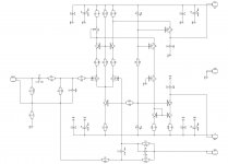
I just came across M-02 / MX-100 front-end and realized it's designed based on the same principles I like to use these days ("Bravo Luxman engineers!"). Besides the jFET input pair (transconductance stage), all the rest of the circuit is controlled purely by current, resulting in rather high slew rate (around 100V/uS with OPS in place), low distortion with excellent profile, low phase shift at 20KHz and excellent stability margins with very light compensation. As a cool bonus - perfect clipping.
My version of the topology uses mostly TO-126 devices - most of them dissipate 150...170mW, except LTP's tail (Q3) - it runs at 450mW.
Besides BF862, 2SK170 jFETs can be used in the input pair (layout needs to be updated in this case).
Luxfront can be used with any OPS, published in this thread.
It's also compatible with Slewmaster OPS boards.
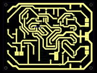
Diy-friendly layout for etching is attached (PDF).
Cheers,
Valery
Sorry - one more pretty cool IPS module 😛
I just came across M-02 / MX-100 front-end and realized it's designed based on the same principles I like to use these days ("Bravo Luxman engineers!"). Besides the jFET input pair (transconductance stage), all the rest of the circuit is controlled purely by current, resulting in rather high slew rate (around 100V/uS with OPS in place), low distortion with excellent profile, low phase shift at 20KHz and excellent stability margins with very light compensation. As a cool bonus - perfect clipping.
My version of the topology uses mostly TO-126 devices - most of them dissipate 150...170mW, except LTP's tail (Q3) - it runs at 450mW.
Besides BF862, 2SK170 jFETs can be used in the input pair (layout needs to be updated in this case).
Luxfront can be used with any OPS, published in this thread.
It's also compatible with Slewmaster OPS boards.
Diy-friendly layout for etching is attached (PDF).
Cheers,
Valery
Attachments
-
z05 Luxfront-00-etching.pdf123.8 KB · Views: 205
-
z01 Luxfront 01.pdf30.2 KB · Views: 199
-
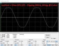 13 Luxfront Clipping 20KHz 84Vpp 01.JPG116.7 KB · Views: 239
 -
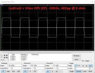 12 Luxfront SQR 28Vpp 01.JPG112.5 KB · Views: 220
 -
 11 Luxfront THD 01.JPG126.4 KB · Views: 510
 -
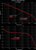 10 Luxfront loop 01.JPG289.3 KB · Views: 529
 -
 04 LuxFront 01.JPG186.8 KB · Views: 559
 -
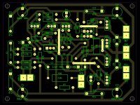 03 LuxFront 01.JPG190.6 KB · Views: 586
 -
 02 LuxFront 01 Sch.JPG92.5 KB · Views: 608
I can see any jfet on your board.....
Marc
Two small blue boxes on picture 3 (bottom traces).
As the board is single-sided and BF862 are SMD, I had to place them on the bottom side 🙂
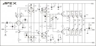
I use this topology for one of my favorite amp SR300 from threadSorry - one more pretty cool IPS module 😛
I just came across M-02 / MX-100 front-end and realized it's designed based on the same principles I like to use these days ("Bravo Luxman engineers!"). Besides the jFET input pair (transconductance stage), all the rest of the circuit is controlled purely by current, resulting in rather high slew rate (around 100V/uS with OPS in place), low distortion with excellent profile, low phase shift at 20KHz and excellent stability margins with very light compensation. As a cool bonus - perfect clipping.
My version of the topology uses mostly TO-126 devices - most of them dissipate 150...170mW, except LTP's tail (Q3) - it runs at 450mW.
Besides BF862, 2SK170 jFETs can be used in the input pair (layout needs to be updated in this case).
Luxfront can be used with any OPS, published in this thread.
It's also compatible with Slewmaster OPS boards.
Diy-friendly layout for etching is attached (PDF).
Cheers,
Valery
http://www.diyaudio.com/forums/solid-state/173462-studio-reference-amplifier-238.html#post4938798
Attachments
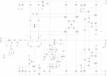
Hi Mile - good one, I like it a lot - based on the right principles. You're using additional mirrors-with-gain stage.
Elegance of a-la Luxman topology - VAS output (transimpedance stage) is driven directly from the folded cascode, assuming both LTP and VAS stage work at the same idle currents (in my case - around 5.3mA). Just a variant - but isn't it cool in its simplicity 😎
Elegance of a-la Luxman topology - VAS output (transimpedance stage) is driven directly from the folded cascode, assuming both LTP and VAS stage work at the same idle currents (in my case - around 5.3mA). Just a variant - but isn't it cool in its simplicity 😎
I like the Luxfront! There's been so many front ends that I've gotten lost long ago. I still have a set of Slewmaster OPS boards here---maybe this is the one that will get me moving 🙂 Any chance there will be a production run of these boards. Learning to etch might induce a case of laziness 🙂
Steve.
Steve.
Hi Mile - good one, I like it a lot - based on the right principles. You're using additional mirrors-with-gain stage.
Elegance of a-la Luxman topology - VAS output (transimpedance stage) is driven directly from the folded cascode, assuming both LTP and VAS stage work at the same idle currents (in my case - around 5.3mA). Just a variant - but isn't it cool in its simplicity 😎
"Bravo Luxman engineers!"
I dn"t know if it is the right....
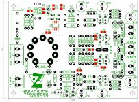
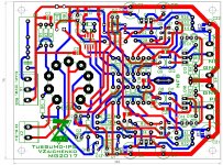
After discussing with gentleman Valery, i decided to give a try to TubSuMo-IPS but actual size is not compatible with other IPS to direct swap.... So i decided to give a try to a new layout. It was not easy to "compress" all in 76x100mm so some smd parts and 2 layer couldn't be take to side....Here is my try to join TubSuMo-IPS to 76x100mm family...
Marc
Attachments
Cool 🙂!
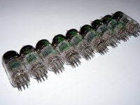
In order to save some space, you could use subminiature double triodes, such as 6111, 6112 or something like that.
Best regards!
In order to save some space, you could use subminiature double triodes, such as 6111, 6112 or something like that.
Best regards!
Cool 🙂!
In order to save some space, you could use subminiature double triodes, such as 6201, 6211 or something like that.
Best regards!
Yes could but i have this stock......
Attachments
- Home
- Amplifiers
- Solid State
- Revisiting some "old" ideas from 1970's - IPS, OPS