Maybe i must create another thread "SA2015 builders"😉
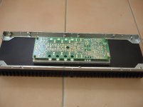
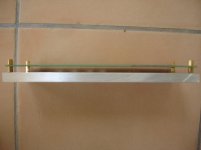
Drilling and tapping alumium plate for spacers.
Drilling and tapping alumium plate for spacers.
Attachments
Last edited:
Maybe i must create another thread "SA2015 builders"😉
Drilling and tapping alumium plate for spacers.
Do you need a drilling helper PDF?
BR, Toni
If it's possible, this will be a big help.Do you need a drilling helper PDF?
BR, Toni
I hope not need to desolder the transistors.
If my memory serves well i think that i must isolate the gnd corners from spacers.
If it's possible, this will be a big help.
I hope not need to desolder the transistors.
If my memory serves well i think that i must isolate the gnd corners from spacers.
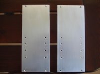
Voila! Attached a drill plan for your heatspreader and your heatsink.
M3 for mounting the PCB and transistors
4 x M4 for mounting the heatspreader to your 2 heatsinks. Or M5 if you are unsure.
And yes - the preliminary (green colored) SA2015 pcb's need to be isolated in the 4 corners with isolation washers...
BR, Toni
Attachments
Thanks Toni, unfortunately the heatspreader already drilled now.
I hope that all is ok.😉
Tapping blind holes is a difficult procedure due to small thickness of the heatsinks.
I hope that all is ok.😉
Tapping blind holes is a difficult procedure due to small thickness of the heatsinks.
Last edited:
...
Tapping blind holes is a difficult procedure due to small thickness of the heatsinks.
You could drill the 4 holes in your heatsink exactly between two fins if you don't have a drill with height regulation...
Sorry,my problem isn't drilling but tapping in these blind holes.You could drill the 4 holes in your heatsink exactly between two fins if you don't have a drill with height regulation...
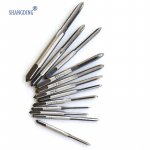
I can't find tapping tools 4mm or 5mm sutch in picture 1.
I have tools as in picture 2.
Attachments

Last edited:
That's what I meant. Tapping for screw would be easier if you drill through the heatsink.
Of course it looks not so professional if you look from the side at the heatsink but you could use black color for your screws to make it hardly visible.
Another variant is you use M4 16mm hex socket steel screws like this one:
Allen screws M4 16 mm Hex socket (Allen) DIN 912 Stainless steel A2 1 pc(s) TOOLCRAFT 888747 from Conrad.com
and mount heatspreaders with those screws from case outside.
It's easier to add a M4 screw thread into the heatspreader.
BR, Toni
Last edited:
Sorry,my problem isn't drilling but tapping in these blind holes.
I can't find tapping tools 4mm or 5mm sutch in picture 1.
I have tools as in picture 2.
That still works for blind holes. Just dril your blind hole deep enough.
I've done this before (with the tools as in pic 2) and works just fine.
I see but would be a problem to find good black screws (visible from the outside).that's what I meant. Tapping for screw would be easier if you drill through the heatsink ...
Yes me too, but at a 10mm alumunium.That still works for blind holes. Just dril your blind hole deep enough.
I've done this before (with the tools as in pic 2) and works just fine.
Please reread post 2350 which I have edited. cross posting ...I see but would be a problem to find good black screws (visible from the outside).
And another variant: carefully and slow drilling exactly at the fins give you more headroom...
Trilobular screws make acceptable plug taps but YMMV in aluminium heat sink material. You can usually save some decent quality items of such screws from old browngoods (VCR's etc.)
I read again but these are stainless steel not black screws.🙁Please reread post 2350 which I have edited. cross posting ...
And another variant: carefully and slow drilling exactly at the fins give you more headroom...
Yes me too, but at a 10mm alumunium.
Sure, the most recent blind holes I did was in 8 mm base of a heatsink with M3 tapping. Works okay.
Just carefully drill as deep as possible in the 10 mm base (in your case). If you're in a fin, just drill drought that as deep as possible.
Alternatively, follow ASTX's advice and try to positon the holes in between the fins. This way you're able to drill all the way through the base.
I will try blind holes between the fins,if it fails i will go for the second option
Last edited:
I hand drill either between the fins, or into the fins. (I don't have access to any pedestal drills at the moment).
Half missing a fin increases the risk of a broken drill when hand drilling.
Very careful feeding with a pedestal drill that does not let the drill drop as it cuts through can drill half into a fin, but it's still risky especially if the drill is not sharp.
If one does drill into the fin, with a drill that is bigger than the fin thickness one ends up with two apertures on the fin sides that allow swarf to escape when it comes to tapping. That allows a taper, or an intermediate, tap to thread form deep enough to give a strong screw hold.
Screws/bolts into steel can use a threaded length as short as 0.7 times the thread diameter, I prefer to regularly removed screws to use a full 1times diameter for the engaged thread length.
In aluminium I recommend at ;east 1.5times the diameter and I generally use 2times for repeated re-screwing
I have many black heatsink with clamping screws that come right through. In use I generally cannot see the bright screw ends unless I deliberately go looking for them. Casual glances do not see the bright ends.
Last edited:
If you find the right black magic marker you can colour the end of the screws black to blend in. Marksalot brand are good for this here. Many others come out purple.
An option to increase thread life in aluminum is to use long set screws as studs and leave them in the heat sinks.
An option to increase thread life in aluminum is to use long set screws as studs and leave them in the heat sinks.
- Home
- Amplifiers
- Solid State
- 2stageEF high performance class AB power amp / 200W8R / 400W4R