🙂🙂
If only the cartridge generator was anything like efficient as a motor, a servo might be made to achieve the same result......?!?
LD
Maybe a useful analogy, I posted some pictures a while back demonstrating the damping of cone motion in a woofer by the motor assembly using a purely mechanical experiment. It is pretty easy to see the damping effect of the main resonance, which in my mind has an analogy to the cartridge motor trying damp the main resonance of the entire arm assembly (~10Hz). Scaling the physics to equate the two systems would give you either a ridiculous speaker or an impossible cartridge arm combination.
A second point is that even with an efficient motor IMO little can be done about damping cone breakup, etc. analogous to cantilever flex, etc.
The emf doesn't depend on L .. only on the flux change.Faraday, actually.
And emf = dΦ/dt = -L di/dt
So dΦ = -Ldi
But why belabour the point. I grovel at your feet for your knowledge of da true Gurus Faraday, Maxwell & Ampere. I totally agree with your point about feeding a cartridge directly into Virtual Earth giving less magnetic distortions.
Your stuff about slew seems airy fairy to someone like me hu kunt reed en rite. 😱
No special laws. You just have to look at it as a 2 terminal generator and everything falls into place.Surely not, quite the opposite. Show us the evidence ?! We've all heard there are special laws of physics for MC carts.......🙄
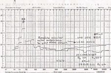
Here's a measurement of noise from Ortofon MC20-II vs VMS20E-II. The B&K 2307 chart recorder has slipped by one tooth so 50Hz hum appears at 40Hz on the trace.
The MC noise is at least 3dB better than the MI on any weighting. The spectrum is nicer too .. MM/MI noise is whitish while MC is pinkish. The preamps is set for very high gain so the noise advantage for the MC is actually even higher.
You can calculate the 'potential' power as V^2/Rdc for a MC.
MM/MI is more complicated cos the Inductance. You have to divide into loadsa frequency bands and at each band transform the series LR parallel C into a parallel L/C/R to get the noise resistance. You then get the 'potential' power in each frequency band. Apply RIAA to taste. You do this even into a virtual earth and you HAVE to take into account the C for noise calculations.
It's exactly the same process as working out the noise of a MM/MI preamp with real cartridge. Guru Wurcer linked to a NS note some time ago describing the details. If you find it download & share please as dem Texans might be trying to erase all trace of NS 😡
If you do this for loadsa cartridges, you'll find the MCs usually have lots more 'potential' power than MM/MI especially in the important 4kHz region. The MM/MI can only get near their 'potential' power (using just Rdc with no fancy calculations) at 1 frequency.
You don't have to realise this 'potential' power to get the potential S/N so this works with either virtual earth or HiZ input amps.
Realising this potential S/N advantage of MCs isn't easy. The preamp in the pic is my 1981 design optimised for very LoZ .. which AFAIK is STILL the lowest noise such beast in the known universe at 0.28nV/rtHz
Attachments
Last edited:
If one says, emf = dΦ/dt = -L di/dt, what about the number of turns N?
In the first expression if for a coil, isn't emf = NdΦ/dt?
And for linked flux, L is proportional to N^2, no?
Also, I'm not clear on why magnetic distortion would be minimized if feeding a virtual earth. In that case, isn't coil current high?
In the first expression if for a coil, isn't emf = NdΦ/dt?
And for linked flux, L is proportional to N^2, no?
Also, I'm not clear on why magnetic distortion would be minimized if feeding a virtual earth. In that case, isn't coil current high?
Well, that's physicists for you.........all constants are 1, and let the engineers sort out the units 😉If one says, emf = dΦ/dt = -L di/dt, what about the number of turns N?
In the first expression if for a coil, isn't emf = NdΦ/dt?
And for linked flux, L is proportional to N^2, no?
Yes, there's a per turn factor in there, but that is dimensionless so is a constant unless we're interested in it.
Thesis is that increasing load current reduces net coil core flux changes, so reduces certain losses such as eddy current loss.Also, I'm not clear on why magnetic distortion would be minimized if feeding a virtual earth. In that case, isn't coil current high?
LD
A negative mass means with F=M*A that when a force is applied, the negative mass will push back, thereby preventing motion.
Is that what you want for the cantilever ?
Hans
Add just enough negative mass to get net 0 mass, then what happens? After all, if lower effective tip mass is better, isn't 0 effective tip mass best? 🙂. What happens when you apply a force to an object with no mass?
Thesis is that increasing load current reduces net coil core flux changes, so reduces certain losses such as eddy current loss.
LD
Here's a bit of a quote on Armature Reaction caused by coil current:
"The armature reaction will reduce the generated EMF due to decrease in value of flux per pole. The iron losses in the teeth and pole shoes are determined by the maximum value of flux density at which they work. Due to distortion in main field flux the maximum density at load increases above no load. Thus more iron losses are observed on load than no load."
Also, I attached a little image below showing what goes on in a motor or generator. It shows (1) field due to stator magnet, (2) field due to coil current, and (3) distorted composite field. In particular, the distorted field incrementally shifts the flux and permeability of the stator magnet, introducing nonlinear distortion in field intensity, and that's the field that induces emf into the coil. Then there is the issue of, "more iron losses are observed on load than no load."
Now, of course these issues have primarily been studied in motors and generators, but a phono cartridge seems like some type of little generator.
So somehow, it seems like you are saying the above effects don't occur in phono cartridges, or they are swamped by some other countervailing effects?
EDIT: There is some more description here: https://www.researchgate.net/post/Armature_Reaction_Effect_in_Synchronous_Generator
Attachments
Last edited:
Intrinsic cartridge noise isn't the point, Richard. In any event it is swamped by mechanical/surface noise performance for all cartridge types, and by preamp noise, especially for MC, unless one works hard as some of you guys do. TI loading of MM/MI works out creditably, FWIW.Here's a measurement of noise from Ortofon MC20-II vs VMS20E-II.
At issue is efficiency and reciprocity of mechanical power conversion. Which is really a mute point as to which of MM/MI/MC has advantage because they are all so inefficient and non-reciprocal as to be negligible.
Yes, one has to take into account cartridge output impedance, RIAA, and programme material spectral content. Even so, there is no pragmatically meaningful difference, and no advantage to MC as claimed. And although transimpedance loading of MM/MI might work out advantageous in principle, it still makes no usable difference.........
That'll be the same aliens who went round erasing my stuff a few years back.......😉Guru Wurcer linked to a NS note some time ago describing the details. If you find it download & share please as dem Texans might be trying to erase all trace of NS 😡
LD
If you go here RIAA Noise Calculator | SYclotron Audio there is a spreadsheet has the NS calculations in a handy dandy auto calculation form.
Thank you, Mark, and also for the links in that web page you posted.Here's a bit of a quote on Armature Reaction caused by coil current:
"The armature reaction will reduce the generated EMF due to decrease in value of flux per pole. The iron losses in the teeth and pole shoes are determined by the maximum value of flux density at which they work. Due to distortion in main field flux the maximum density at load increases above no load. Thus more iron losses are observed on load than no load."
So yes, net flux is reduced by load current, and in principle that can distort the applied field's uniformity leading to distortion.
Thinking further about it: in a cartridge, reduced flux should reduce coil emf, ie increasing load current should reduce coil emf. However, on the face of it this doesn't typically happen with MM/MI carts, such as the result George posted comparing Hagerman preamp conventional loading with Aurak TI: f response for RIAA encoded programme test records in the audioband was much the same.
This could be because load current is typically trivially small cf armature flux changes, so even significant differences don't affect coil core flux nor generated emf? Even in transimpedance loading, MM/MI coil output impedance is not very low in the scheme of things, and that determines load current. As George asks, 'where does the reciprocity break?'
In which case, there would be no significant effect on distortion, through neither distortion of applied field, nor eddy current changes, because net flux would remain much the same.
Interesting, methinks.
LD
Last edited:
LD, IF the different cartridge types are 'the same' according to these figures then we are left with the other advantages, cost, replacable styli etc.. Right? I think you are right especially with TI amp now part of it all.
Yes, that's much as I see it. Of course performance essentials such as stylus, suspension, cantilever etc etc need to be in place.LD, IF the different cartridge types are 'the same' according to these figures then we are left with the other advantages, cost, replacable styli etc.. Right?
Also, mechanical top resonance needs to be above the audioband, ie not used to prop up losses in generator or post resonant LCR roll-off in MM/MI. Otherwise TI loading will expose it.
And the cartridge engine needs to be able to cope with extra current load without distortion. I think, from recent discussion, one might begin to understand why that might be.
So not all MM/MI carts are equal in tolerating and performing well in this. Nor, in principle, are all MC carts immune to top resonance in the audioband or generator losses.
Makes me think better cartridge mechanics/generator/preamp combination topologies are still latent and there to be had........
LD
well of course there are strain gauge designs that are position rather than velocity sensitive.
Personally (and I am easily pleased) I think that, between the Cordell/van Raalte loading concepts and TI loading we have a couple of methods for levelling the field between MM and MC which is good. Swinging the eye of Sauron onto MC as well at some point might be a good thing as I have a 6 Ohm ortofon that needs a rebuild. But that should maybe be another thread 🙂.
Personally (and I am easily pleased) I think that, between the Cordell/van Raalte loading concepts and TI loading we have a couple of methods for levelling the field between MM and MC which is good. Swinging the eye of Sauron onto MC as well at some point might be a good thing as I have a 6 Ohm ortofon that needs a rebuild. But that should maybe be another thread 🙂.
Yes, like the Panasonic EPC 451 etc. That should expose any mechanical top resonance, but also might have mechanical resonance of it's own in the transducer I suppose.well of course there are strain gauge designs that are position rather than velocity sensitive.
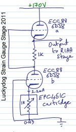
Seeing Scott's recent minimalist preamp, reminded me of my ultra minimal strain gauge phono preamp, another one from the archive. Complete in one valve (double triode) and one resistor, and ready for RIAA nudges via digital eq........ it works very well 🙂
For the purists, FETs are fine of course !
LD
Attachments
whilst we are off topic in strain gauge land I was musing a while back that, as well as being able to measure VTF whilst a record is playing a strain gauge setup should be able to measure anti-skate in real time and provide feedback to and active anti-skate. Shame that the soundsmith carts are so expensive and they insist you buy their pre-amps.
If you go here RIAA Noise Calculator | SYclotron Audio there is a spreadsheet has the NS calculations in a handy dandy auto calculation form.
The noise calculator you refer to, computes S/N without weighting.
However unweighted S/N figures are rather useless because they do not correspond in any way to what we are hearing.
That's why A-weighting or dBA is mostly mentioned for audio equipment when referring to noise figures.
It is possible to build an excel sheet where all important parameters can be entered, which is what I did for MC cartridges.
However using LTspice is much more accurate and versatile because it can easily use very small frequency bands and also include current noise and A-weighting.
LTspice also takes into account the 1/f voltage and 1/f current noise.
The model below can universally be used for MM and MC cartridges.
All parameters can be entered like Lcart, Rcart, Rload and Cwiring.
Parameters for the amp to be used, in this case an OP27, can be entered as En, Enk, In and Ink, explanation is within the model.
After having plotted the A-weighted input noise, move the mouse to the label of the trace, hold down the control key and left mouse click.
What you then see is the accumulated A-weighted input noise from 20Hz to 20Khz, in this case 545nV.
Now with your calculator compute the S/N with the figure provided by LTSpice.
Let's say that for this MM cart, output is 5 mV@1Khz @5cm/sec.
S/N is now 20*log(5e-3/545e-9) = 79.3 dBA as the absolute maximum achievable S/N.
Simple, quick and accurate.
Change the OP27 for the very low voltage noise AD797 and maximum achievable S/N will be 71.3 dBA.
Take a complete noisefree amp and maximum achievable S/N will be 81.0 dBA.
The above figures are computed with the Cart connected.
Usual figures provided by phono preamp manufacturers are with shorted inputs and are of course much better, but a bit misleading.
(P.S. En for the AD797 in the example list must of course be 0.9e-9 instead of 0.9e-12)
Hans


But it is weighted, it even says 'Updated at the suggestion of Hans P'!
Note: not saying LTspice isn't better, just a spreadsheet can be convenient for those of us with 2 left hands when it comes to LTspice 🙂
Note: not saying LTspice isn't better, just a spreadsheet can be convenient for those of us with 2 left hands when it comes to LTspice 🙂
Last edited:
But it is weighted, it even says 'Updated at the suggestion of Hans P'!
I asked SY to fix the RIAA issue I don't think he did the weighting though there are those that prefer IEC weighting.
BTW Hans I prefer to make noiseless resistors with VCCS's of gm = 1/R tied to their own inputs instead of Laplace sources. That way I can use any cookbook filter and do any kind of analysis like transient with the same circuit. You can also sim a circuit selectively turning off the noise of some of the resistors.
IMHO the shorted noise is far less useful than the correct unweighted noise.
Last edited:
Remember post #613 ? http://www.diyaudio.com/forums/analogue-source/303389-mechanical-resonance-mms-62.html#post5051795
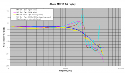
Same 24/96Krecordings, flat amplification, this time I did 128 points FFT, so the traces were very smooth. I read the data at 47 frequency points 1KHz to 48KHz and made the diagram you see below.
Nothing special but I made it for to compare the cartridge when reading the test tracks (mechanical, magnetic and electrical circuit frequency response) and the cartridge on air when excited by the 50 Ohm signal generator (electrical circuit frequency response).
On test recordings, anything above 20KHz consists of harmonics (for the most part they are engraved on the grooves, for the lesser part they are due to playback cartridge).
Soft band limiting on HFN frequency sweep track (yellow trace) and hard band limiting on all other tracks.
Cartridge loading when reading tracks :47Kohms// 150pF
Cartridge loading when driven by the 50 Ohm signal generator :47Kohms// 220pF
George
Attachments
It would be MUCH more useful to plot the spectrum of the noise and allow comparisons of spectrum & level.The noise calculator you refer to, computes S/N without weighting.
However unweighted S/N figures are rather useless because they do not correspond in any way to what we are hearing.
That's why A-weighting or dBA is mostly mentioned for audio equipment when referring to noise figures
....
loadsa good stuff
A weighting is a poor estimate of audible noise ... especially as found in mikes & electronics. But it's enshrined in historical record and cos it gives the best 'numbers'. Ray Dolby suggested a much better method in the 80s which used the IEC 468 (?) weighting and an average reading meter which had MUCH better correlation to what we hear & object to ... but was shouted down by the makers who wanted their nicer dBA numbers.
Many true noise gurus like Eric Benjamin & ?? prefer just to look at noise in the 4kHz 8ve or 1/3 8ve ... especially for stuff where the noise spectrum is wonky as we have in vinyl playback systems.
Average reading is irrelevant today as practically ALL modern noise measurements will use a FFT and thus be 'true' RMS.
Spectral plot of the noise please. Make sure the plot distinguishes clearly between
- 'constant bandwidth' eg FFT noise plot
- 'constant relative bandwidth' eg 1/3 octave filters
Last edited:
- Home
- Source & Line
- Analogue Source
- mechanical resonance in MMs