Hi Valery,
I loaded those gerbers/drills, for the VHEX designs, they look fine to me upon a first glance.
In the schematic I see a R symbols, some "<" and some ">" 🙂 I assume that they are rotated 180, you did not have them in your legend that you supplied the other day, what are those wattages?
Mouser has these
0.22/3W 660-MOSX3CT631RR22J for $0.288CDN and
0.22/5W 660-MOSX5CR22J 5W for $1.34CDN
For those diodes, 1N4004, is it not best for them to be a fast recovery type? something like UF4004 and is a 1A diode sufficient in size for the o/p stage back emf clamp diode?
Thanks
Rick
Hi Rick,
Those resistors are 5W. As you can see from the board outline, two different types of resistors can be used - cement ones (longer body) and plastic ones (shorter but taller body).
I used 1N400X countless number of times at these positions - never had issues like damaging them or something. Fast recovery is an advantage in general, but in case back emf clamping really happens - that's a rather "bad" extraordinary operating condition, so I consider possible slightly slower recovery as ok.
Cheers,
Valery
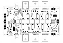
VHex+ OPS - PDFs for etching (2P and 3P)
PDF files for etching - all variants.
Have fun!
Val
PDF files for etching - all variants.
Have fun!
Val
Attachments
-
 00-2P-etching-screen.JPG145.3 KB · Views: 492
 -
08-VHex-OPS-3P-01-etching.pdf46.4 KB · Views: 271
-
07-VHex-OPS-3P-01-etching.pdf46.3 KB · Views: 142
-
06-VHex-OPS-3P-01-etching.pdf27.8 KB · Views: 144
-
05-VHex-OPS-3P-01-etching.pdf27.8 KB · Views: 164
-
04-VHex-OPS-2P-01-etching.pdf40.8 KB · Views: 199
-
03-VHex-OPS-2P-01-etching.pdf40.7 KB · Views: 168
-
02-VHex-OPS-2P-01-etching.pdf24.6 KB · Views: 197
-
01-VHex-OPS-2P-01-etching.pdf24.5 KB · Views: 179
-
 00-3P-etching-screen.JPG171.7 KB · Views: 484
Valery:
Have you ever considered error-correction added to these output stages?
mlloyd1
Hi Mlloyd, a good question - of course I did 😀
However, I'd like to perform proper testing before I show the feed-forward EC solution for these output stages. My plan is to see highly accurate spectrums and do some listening with EC on and off in order to assess if it's really worth some extra parts.
I will let you know how it goes. If you would be interested to perform this kind of test as well - please PM me 😉
Cheers,
Valery
Hi Andrew and All,
Please see the good-matching OPS section documents attaches - 2-pairs and 3-pairs OPS options.
Optimal rails for 2-pairs OPS = +/-50...60V DC
Optimal rails for 3-pairs OPS = +/-65...75V DC
NOTE! Different rails require some resistors'value adjustment in Lichtstark front-end module!!! Let me know the rails you are going to use - I will let you know the values.
No changes in the OPS though.
Also note! Connectors on Lichtstark IPS and VHex OPS modules are mirrored with regards to each other! If they are placed one next to the other, IPS module has to be mounted either upside-down, or 90 degrees.
Cheers,
Valery
Can you tell me where is the whole schematic for this amp?
Can you tell me where is the whole schematic for this amp?
Hi Carlmart,
If you're looking for the full amplifier (front-end + OPS) - that's what we call Lichtstark-X - see the schematic >HERE - post#1884<
I will update the first page of this thread soon for easier navigation.
Cheers,
Valery
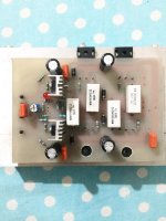
Just a rough output stage for test😉
Not bad 🙂
Will you place the bias multiplier transistor under the board?
Hello vaizchenko
greetings yes mje340 will be under the pcb its just a test pcb if
everything goes ok a new pcb can be designed IPS / OPS on one pcb
warm regards
Andrew
greetings yes mje340 will be under the pcb its just a test pcb if
everything goes ok a new pcb can be designed IPS / OPS on one pcb
warm regards
Andrew
+/-50V adjustments
Hi Marc!
Please see attached - adjusted values are marked with the red frame.
Total - 6 resistors, all of them are 1W.
OPS does not require any changes.
Cheers,
Valery
Hi Valery could you provide value for +/-50VDC for both LS-IPS and VHex-OPS....
Marc
Hi Marc!
Please see attached - adjusted values are marked with the red frame.
Total - 6 resistors, all of them are 1W.
OPS does not require any changes.
Cheers,
Valery
Attachments
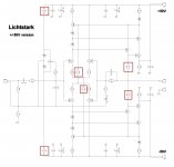
Hi Marc!
Please see attached - adjusted values are marked with the red frame.
Total - 6 resistors, all of them are 1W.
OPS does not require any changes.
Cheers,
Valery
Thanks Valery.
Marc
Hi Carlmart,
If you're looking for the full amplifier (front-end + OPS) - that's what we call Lichtstark-X - see the schematic >HERE - post#1884<
I will update the first page of this thread soon for easier navigation.
Cheers,
Valery
Nice!
Are there other options suggested for the IPS stage, perhaps something "Goldmund like" in LTP and VAS?
Hello vaizchenko
greetings will be using 57 volts dc +/- do i have to change the 6 resistors
to 1 watt as described in post #1992 y have all the values 1 watt
warm regards
Andrew
greetings will be using 57 volts dc +/- do i have to change the 6 resistors
to 1 watt as described in post #1992 y have all the values 1 watt
warm regards
Andrew
Nice!
Are there other options suggested for the IPS stage, perhaps something "Goldmund like" in LTP and VAS?
Hi Carlos,
Then I would recommend VHex+ design - see these posts >HERE< and >HERE<
Current-driven VAS is excellent performer. Here is the schematic and information on PCBs ordering (shipping is $15): VHex+ amplifier
Let me know if you will have questions 😉
Cheers,
Valery
Hello vaizchenko
greetings will be using 57 volts dc +/- do i have to change the 6 resistors
to 1 watt as described in post #1992 y have all the values 1 watt
warm regards
Andrew
Hi Andrew,
For +/-57V better use those 1W resistors' values from post#1884.
Cheers,
Valery
Not exactly. I was referring to something like this.
Attachments
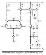
Not exactly. I was referring to something like this.
OK, how do you like this one?
Attachments
- Home
- Amplifiers
- Solid State
- Revisiting some "old" ideas from 1970's - IPS, OPS