Thanks delange.
Exactly - thanks Andrew.
I'll have a look if the original heatsink holes are anodised. If not, then I already have M3 bolts x6mm depth connected by steel bracket. Why would I need to add wire to that?
I don't think any screws involved are anodised except for top and bottom covers... So I will have to put a bolt through the top cover, or else change screws to bolts and add nut/washer and crimpring on the inside. Will have to removed the anodised coating to get good contact under the washer because the covers and their holes are only 3mm thick/ deep.
I would like to avoid an ugly great screw sticking out the top of the amp...
Pops
A screw into a tapped hole can be this connection.
I have not seen tapped holes that are anodised down the threads.
Exactly - thanks Andrew.
I'll have a look if the original heatsink holes are anodised. If not, then I already have M3 bolts x6mm depth connected by steel bracket. Why would I need to add wire to that?
I don't think any screws involved are anodised except for top and bottom covers... So I will have to put a bolt through the top cover, or else change screws to bolts and add nut/washer and crimpring on the inside. Will have to removed the anodised coating to get good contact under the washer because the covers and their holes are only 3mm thick/ deep.
I would like to avoid an ugly great screw sticking out the top of the amp...
Pops
My Q-Watt as of 16th March 2017
Great work Calpe - looking really good. Does it work?
Mine is in pieces again for drilling.
Pops.
Does it work?
No comment popchops!
In my lunch-breaks trying to tackle a small problem with the supply lines
I'll keep fellow Q-Watt assemblers posted when i have some news.
As for the case, i'm doing some resistance checks between the different pieces of the case when mounted and take it from there.
I'm not prepared to spoil such a nice case.
Last edited:
popchops, i queried the matter with the case supplier and they have replied - 'our engineer suggested to remove the anodization where the screws are placed.'
popchops, i queried the matter with the case supplier and they have replied - 'our engineer suggested to remove the anodization where the screws are placed.'
Good to know - thanks Calpe. I need to get a little wire brush bit or something for my drill. Pops.
Anodise is quite hard. Much harder than the aluminium.
It's the same stuff they glue onto paper to make aluminium oxide "sandpaper".
You would be better scraping the anodise off with a sharp knife. Then apply a grease/oil/coppaslip to prevent the aluminium oxidising again.
It's the same stuff they glue onto paper to make aluminium oxide "sandpaper".
You would be better scraping the anodise off with a sharp knife. Then apply a grease/oil/coppaslip to prevent the aluminium oxidising again.
Aluminium oxide (Al2O3) not only is quite hard, but basically also a good insulator. That's the reason why it needs to be removed to ensure good electrical connection.
Best regards!
Best regards!
Thanks.You would be better scraping the anodise off with a sharp knife. Then apply a grease/oil/coppaslip to prevent the aluminium oxidising again.
Just to pass on my thanks to delange for all his help and guidance with the voltage guard Cct and my SMPS's.
It's great that people who have also constructed the Q-Watt go out of their way to help others.
Just to mention that anyone using a SMPS (switched mode power supply) need to apply a load so that they supply the current stated for the SMPS.
I used two 330R 5W's on the 55v o/p's to ensure that more than 110mA was drawn.
That means the SMPS you're using aren't stable at just the load of an idling Q-Watt? How do they behave then? *iirc* Delange uses the same SMPS model and didn't report an issue?
Best regards!
Best regards!
No, the SMPS are very good quality, but I should have realised testing their 16v @ 500mA will only give correct current if there is a load on the 55v lines.
Let's not put people down, when they go out of their way to help!
My mistake and no one else's
Let's not put people down, when they go out of their way to help!
My mistake and no one else's
No, I surely didn't want to attack anyone here 🙂. But now it is clear to me what you've meant. Thanks!
Best regards!
Best regards!
Just to pass on my thanks to delange for all his help and guidance with the voltage guard Cct and my SMPS's.
It's great that people who have also constructed the Q-Watt go out of their way to help others.
Just to mention that anyone using a SMPS (switched mode power supply) need to apply a load so that they supply the current stated for the SMPS.
I used two 330R 5W's on the 55v o/p's to ensure that more than 110mA was drawn.
With pleasure Calpe!
That means the SMPS you're using aren't stable at just the load of an idling Q-Watt? How do they behave then? *iirc* Delange uses the same SMPS model and didn't report an issue?
Best regards!
The SMPS's work like a charm.
What Calpe experienced was during initial testing: his Q-Watt amplifier was not connected to the SMPS main output. At the same time he was testing if the modification for the speaker relays worked. But when the SMPS has no load at their main output, the aux supply enters a "burst mode". The result is that the aux output voltage drops by 3 volts. That was a bit confusing and let us to believe Calpe had an issue somewhere in the relays modification.
But as soon as the Q-Watt is hooked up to the SMPS main output (even when idle) the SMPS aux output voltage is normal (16 volts).
That means his 330R 5W resistors aren't needed at all?
Best regards!
Those resistors are only required when the Q-Watt is not connected while testing the aux supply.
Once the Q-Watt is connected there is enough load on the main supply for the aux supply to function correctly
To meet the SMPS minimum load criteria, I would think that you would increase the ops bias current in order to meet it. So that would be 55mA of bias per channel. Nothing wrong with that, you have an amp that has a much larger class A region. To me it is a waste of power dissipating the power in a passive resistor.Just to pass on my thanks to delange for all his help and guidance with the voltage guard Cct and my SMPS's.
It's great that people who have also constructed the Q-Watt go out of their way to help others.
Just to mention that anyone using a SMPS (switched mode power supply) need to apply a load so that they supply the current stated for the SMPS.
I used two 330R 5W's on the 55v o/p's to ensure that more than 110mA was drawn.
To meet the SMPS minimum load criteria, I would think that you would increase the ops bias current in order to meet it. So that would be 55mA of bias per channel. Nothing wrong with that, you have an amp that has a much larger class A region. To me it is a waste of power dissipating the power in a passive resistor.
Once again, those resistors are only required during the testing phase (aux supply without any load connected to main supply).
As soon as the amp is connected to the the SMPS those resistors can be omitted.
Hey folks!
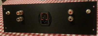
Just finished the back panel drilling for my Q-Watt amp! Panel is 373mm x 120mm x 3mm.
Pops.
Looking good popchops. I take it you're getting near to completion?
- Home
- Amplifiers
- Chip Amps
- My Q-Watt project